Sunday, February 26, 2017

Interpretation of Intrusion Alarm Power Supply

Interpretation of Intrusion Alarm Power Supply

BS EN 50131-6: Alarm systems Intrusion and hold-up systems: Part 6: Power supplies, was revised and re-issued as EN50131-6:2008.

This document has been prepared to give guidance on the interpretation of some of the clauses in the standard that are in need of further clarification. It is intended that this guideline can be used by manufacturers to self- certify their products to conform to the standard. This guidance document may be further revised as required.

Only those items in BS EN50131-6: 2008 that have been the subject of formal comment by BSIA members are listed below. All other clauses or parts of the standard are believed to be self-explanatory. 

Advisory note:
This guide has been produced for use in PD6662:2010 Scheme for the application of European standards for Intruder and Hold up alarm systems. BSIA has produced other guides specifically for the PD6662:2004 Scheme, which may not be appropriate for this scheme.  Therefore you should seek the appropriate guidance.  

Power Sources
There is inconsistent usage of PPS (Prime Power Source) and EPS (External Power Source) in the EN50131 series of standards.

Figure 1 shows the relationship between each of these entities, as used within the standard. Essentially the PPS is the national grid mains supply. In those installations having a standby generator capability e.g. hospital, then the standby generator is the SPPS. The (mains) power input to an I&HAS may come from either source (PPS or SPPS) of which the I&HAS may have no knowledge and this input is therefore generically known to the I&HAS as the EPS.

The APS is typically represented by any local standby power source (e.g. rechargeable battery) within the design and control of the I&HAS that can power the I&HAS (or part thereof) for a predetermined period of time in the event of loss of the EPS. Note that from EN50131-1 clause 9.2, if an SPPS is automatically switched into operation on loss of the PPS, the overall system standby period from the APS is reduced to 4 hours for I&HAS grades 2, 3 and 4.

EN50131-1 and TS50131-7 do not use the term “EPS” and refer to the immediate power source of the PS consistently as the “PPS”. 

Power Supply Rating
The rating of the power supply (PS) is the total continuous output current capacity of the PS when operating under all conditions of EPS or from a SD of capacity as defined by the PS manufacturer for a grade dependent time. This is the output current that is available to power system components and does NOT include the additional current that is used by the PS to recharge any attached storage device. Note that where the PS is integral to another component e.g. a CIE, then the rating of the PS should exclude the CIE and the manufacturer should declare the CIE current consumption separately as a system component.
Note: the PS manufacturer must clearly state in the product documentation that the total PS rating must not be exceeded where independent power outputs have continuous rated outputs, the sum of which is greater than the total PS rating e.g. multiple fused connections.

Interpretation (ব্যাখ্যা) of clauses
Clause 3.1.4 independent power outputs
This clause refers to completely independent outputs from a power supply where a short circuit and/or overload on one output will have no affect on the others. Each output may have multiple connections. Simple fused outputs may not qualify as being independent if an overload or short circuit on one has an effect, even if only transitory (e.g. during finite time for fuseable link to fail), on another.


For the purposes of this interpretation the following diagram gives a typical example.
Example general arrangement of PS and CIE with independent outputs
In the example shown in Figure 1, O/P 1 and O/P 2 may only be considered independent power outputs if applying a short circuit or overload to one will have no effect on the other. Although the CIE module is connected to the output of the regulating element, this connection is not considered an independent output of the PS for the purposes of the tests of clause 8.2.


Clause 4.3 APS Capability
Note that there is no longer a table within EN50131-6 for standby capability.
This is replaced by the simple requirement that the PS must be capable of meeting the system requirement of EN50131-1, Table 23.

Clause 4.11 Tamper security
There is inconsistency between the requirements of EN50131-6:2008 and those for CIE in EN50131-3:2009. For consistency, the requirements of EN50131-3:2009, clause 8.7 should be applied.

Clauses 7.19-7.22 Tests (Tamper security)
These tests should be replaced by those from EN50131-3:2009 clause 11.9 (see clause 4.11, above).


Saturday, February 18, 2017

HOW TO USE IP CAMERA ALARM I/O

How to use ip camera alarm i/o
As we know, professional IP cameras have alarm input and output interface for security integration solution. Users can use this interface to connect other security devices such as PIR motion sensor, door sensor, perimeter beam sensor...etc. This article is intended to give a guideline for connecting alarm input/output interface of Vivotek, Axis, Sony, HikVision, Dahua, Messoa,...and more IP cameras. 

KNOWING ALARM I/O (INPUT / OUTPUT)
Alarm Input / Alarm Output is a pair of pins in camera's terminal block or connector through which it's possible to connect electronic device with the camera. Alarm Input receives signal from external device, will be triggered from external device if something changes, and Alarm output notifies the external device by the camera upon a event (motion detection, vandalism, video loss).

The terms "Alarm In / Alarm Out" are mainly used as the application for alarm system, but they are also called digital input (DI) / Digital Output (DO) as the common terms.

External device connected to Alarm In can be a switch (or say relay), button or any device which can issue a trigger signal. External device connected to Alarm Out can be a light, alarm horn/siren or any kind of device which receives data.

SHOULD I USE CAMERA'S ALARM I/O?
The main benefit of using camera's Alarm Input / Alarm Output is to respond to the event instantly and automatically by a pre-defined event scheme, and give alert message immediately so that the monitoring control center can handle any situation in a short time to reduce hazard.

CAMERA'S ALARM INPUT/OUTPUT
(1) Terminal Block Type: use 2-pin connector to connect wire
Dahua IP Camera - Terminal Block
Hikvision IP Camera - Terminal Block
Messoa IP Camera - Terminal Block
(2) Connector Type: connect wire directly
*Alarm Out (Orange): Connect to a device that responds to alarm signals, such as buzzers or lights.
*GND: Ground (electricity) in electrical circuits
*Alarm In 1 (Red) & 2 (Brown): Connect to devices that issue alarm signals. Up to two (2) input devices can be selected.
Messoa Camera Alarm Input / Output
CONNECTION EXAMPLE 
1.      Connect Alarm In via a switch to GND: Simply  connecting  Alarm In_1  via a switch to  GND with a single wire,  as shown above, the  Alarm In_1 will be instantly triggered by a press on switch. You do not have to have an external battery to make the “switch” work.
The example circuit of Alarm In: Alarm In 1 –> Switch (OPEN by default) –> Ground
2.      Connect Alarm Out: The Alarm out is an open-drain structure, so you have to  supply external power source  to make the function work.
The example circuit of Alarm Out: DO 1 –> LED (load) –> +[battery]- –> Ground
3.      Enable External Alarm: Access the IP camera via Internet Explorer, go to camera's configuration page to enable External Alarms. Enable the Alarm In/Out that is connected with external alarm devices and set the voltage level as low or high to define the active state.
4.      Validate the setting by pressing the switch and check if it triggers the LED instantly.
The alarm output ports on the back of IP camera can be connected with a siren or strobe light. Below it's a connection example. The goal is to turn the siren/strobe light on when an alarm is triggered. The working theory is pretty simple, you can imagine the alarm output is a turn on/off switch. In below connection diagram, you need to use extra power supply (for example a AC/DC adapter) to provide the power for strobe siren.

For DVR Click at DVR Alarm
The IP camera's alarm inputs are grounding alarm inputs (Normal open or Normal close type). Hardwired sensor or device can parallel connect ground (-) end and COM end of the alarm detector, while parallel connect the NO (+) end and NC end of the alarm detector. (Please note that you need to provide external power to the detectors)
In the above connection diagram, the DG85 (motion sensor)'s NC connects the positive (+) alarm input of IP camera, and the DG85 (motion sensor)'s COM (or GND) connects the negative (-) alarm input of IP camera. (This is NC connection, you need to choose the IP camera's alarm input property to NC.)
You can make connection between IP camera and hard-wired/wireless alarm panel. Connect the alarm output of IP cameras to hardwired zones of alarm panel. Please note that you need to use the EOL resistor in this connection. The EOL resistor can protect the circuit of wiring to prevent short-circuit or cut. The EOL resistor should be installed in the end of IP camera.
With correct connection, the IP camera can send signal to alarm system for associated alarm action.
Two different connection are available:
1.      When alarm output (IP camera) is NC:You need to do the normal close connection. The EOL resistor should connect into circuit in series connection.
2.      When alarm output (IP camera) is NO: You need to do the normal open connection. The EOL resistor should connect into circuit in parallel connection.


Normal Open (NC) and Normal Close (NO) explanation
Normal Open: When the device is in the non-triggered state, it's normally closed means that the circuit can allow current to flow from NC to COM, or it turns ON. When the alarm is triggered, the relay is enabled and it will switch from the normally closed (NC) to normally opened (NO) or from Turn ON to Turn OFF.

Normal Close: When the device is in the non-triggered state, it's normally opened means that the circuit is open, it doesn't allow current to flow from NO to COM, or it turns OFF. When the alarm is triggered, the relay is enabled and it will switch from normally opened (NO) to normally closed (NC) or from Turn OFF to Turn ON.


Saturday, February 4, 2017

Factors to Consider When Purchasing a PTZ IP Camera

Factors to Consider When Purchasing a PTZ IP Camera

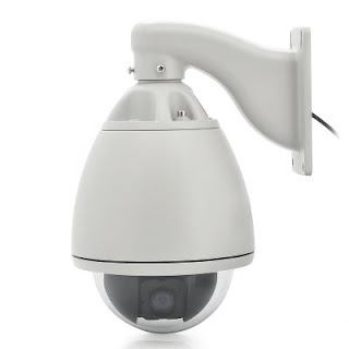
PTZ IP cameras are commonly used for surveillance in large home compounds and public areas such as commercial car parks, stadiums and conference halls. PTZ stands for Pan Tilt Zoom, and that means you can use the IP software for cameras through the internet or your network to manipulate what the IP camera displays.
Different IP camera brands sport different kinds of zooms, and lower end cameras will simply feature the digital zoom. Proper optical zoom is the recommendable zoom type and this, together with the price, will always be specified in the product description.
Basically, a PTZ IP camera lets the user view real time images of the protected areas over the internet. You can simply monitor your office, home, building, yard or anywhere from miles away using a PC or a high end smartphone, tablet or PDA. Some network cameras even feature built-in Web server functions such that the IP camera doesn’t necessarily need to be connected to a computer.

DESIGN
IP PTZ cameras are traditionally spherical in shape, and this is mainly because they are meant to be completely mobile. Either the network camera itself (the sensor and camera mechanism) has been designed to take the shape of a sphere, and held so that it can pivot accordingly, or the camera is structured more traditionally and cased in a spherical protective bubble where it can tilt, pan and zoom and take images from within the shield.

NIGHT VISION
IP cameras with night vision capabilities come with built-in LED lighting to enable object visibility in dark settings, or at night. For outdoor surveillance, specifically in places without artificial lighting, night vision cameras may come in handy.

PTZ vs PT
Some IP cameras can only pan and tilt but not zoom. The two functions will usually be enough if the area you want to cover is small, like, say, your living room. However, if you want to cover a large area such as a shopping mall, an IP camera with the zoom function will be more effective.

HOW DO THEY WORK ?
PTZ IP cameras are typically controlled using remote systems. Users can do an initial configuration to have the camera moving and rotating in a certain predetermined pattern, or do it manually using a keyboard or mouse controlled interface. The angle of the lens can also be manually controlled, and this facilitates automatic position adjustment of the camera.
BENEFITS OF PTZ IP CAMERAS
·         User does not need to be close to the camera to operate it.
·         Requires little maintenance after it has been installed (except for regular cleaning of course).
·         Has 360-degree mobility. This way, it can detect and track objects as they move in the covered area as long as the target object is within lens range.

Factors to Consider When Purchasing a PTZ IP Camera
INDOOR OR OUTDOOR USE ?
If you’re looking for a PTZ IP camera for outdoor surveillance, you need one with night vision, weatherproof enclosure, miniature architecture for “outsider” visibility reasons, and vandal-proof capability for fortification in high crime areas.

YOUR DESIRED CAMERA FORM FACTOR
Each form factor has its own benefits, and the brand you opt for should cover all your surveillance requirements. Would you prefer a dome-shaped or an inconspicuous mini-dome camera? A wireless option or just an ordinary corded PTZ IP camera? You know your place and specifications best.
LEVEL OF DETAIL
When weighing different camera alternatives, you need to be sure of the detail level you want to see in your images. For wide area surveillance, you need a higher resolution, of course, as this will allow you to view even the furthest of images in relatively great detail.
Another factor that affects a camera’s resolution is its field of view (FOV). This is the viewable expanse of a given scene taken by the camera, and is sometimes referred as the angle of coverage or angle of view. A small FOV generally leads to the target object appearing smaller than it would in a fairly larger FOV.

The type of lens featured in the camera will also have an impact on resolution and field of view alike. A lens with low focal length number will bring about a wide field of view but less magnification while a higher focal length number will provide more magnification.

PTZ IP cameras, just like ordinary cameras, come with different resolution capabilities, and if you choose a high-resolution one, you also need to choose a high resolution megapixel lens so that the resolution required to produce a clear and detailed image can be maintained. If you combine a high resolution camera sensor with a less powerful lens, then your images will not be as detailed and crisp as you may desire.
POWER
PTZ cameras have multiple motors built-in which draw a considerable amount of power compared to a regular surveillance camera. Power can be supplied locally at the camera location or a cable can be pulled from a power source to the camera. The size of the wire dictates the maximum distance the cable can extend from the camera to the power source. See the chart below.
·        12 Gauge Wire – Maximum Distance 320 Feet
·        14 Gauge Wire – Maximum Distance 225 Feet
·        16 Gauge Wire – Maximum Distance 150 Feet
·        18 Gauge Wire – Maximum Distance 100 Feet


Each PTZ camera is shipped with its own power supply. Some cameras operate on 12v DC and some on 24v AC. Make sure you note the type of power the camera uses and that the power supply matches the camera.