Saturday, November 23, 2013

CCD Sensor Operation in Camera

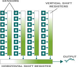
This diagram illustrates the general layout of the most common type of CCD array, the Interline Transfer CCD. The CCD is composed of precisely positioned light sensitive semiconductor elements arranged as rows and columns. Each row in the array represents a single line in the resulting image. When light falls onto the sensor elements, photons are converted to electrons, the charge accumulated by each element being proportional to the light intensity and exposure time. This is known as the integration phase. After a pre determined period of time the accumulated charge is transferred to the vertical shift registers.

In cameras conforming to the video standards mentioned above the charge transfer to the vertical shift registers is accomplished in two stages. Initially the charge in the odd numbered rows is transferred, followed by the even rows. Next the charges in the vertical registers are shifted into the horizontal shift register and clocked to the CCD output. Consequently all the odd rows are clocked out first (odd field) followed by all the even rows (even field). The rate at which the charge from the horizontal shift registers is clocked out is governed by the number of elements (pixels) per row and the video standard the camera complies with.
An inherent problem associated with the interline transfer CCD lies in the fact that the vertical shift registers running across the array are insensitive areas and as such act as blind spots. One way of overcoming this is to fabricate micro lenses over each element thereby increasing the effective area of the cell. The lenses also help with the smaller format CCD. Because of the electrical characteristics of the semiconductor substrate on which the CCD is formed each cell has an absolute minimum separation from adjacent cells. Therefore smaller CCDs require smaller cells. Reducing cell size reduces the amount of accumulated charge, using lenses increases the incident light.
Another way of overcoming the problem caused by the vertical shift registers is to do away with them and utilize a different charge transfer mechanism. Frame Transfer CCDs do exactly that. This type of CCD has a separate storage area into which the charge is directly transferred from each cell. This process has to be performed rapidly in order prevent blurring as transfer occurs during the exposure time. Once in the storage area the charge can be clocked out in a similar manner to the interline transfer device.
Thursday, November 7, 2013

Splice the Wires for a Security Camera

Splice the Wires for a Security Camera

Security cameras need two types of cables to operate.
1.       Power supply cable and
2.       Video cable.
Wireless security cameras do not require a video cable but they do require the power supply cable. The power cable transports 12V DC, low-voltage power from the transformer, which is plugged into an 220VAC ~ 110VAC power outlet, to the camera. This cable has two 18 gauge wires, a positive wire and a negative wire, both inside a single jacket. The negative wire will be marked with a black or white stripe. The video cable is a RG-59 / RG6 / RG11: coaxial cable which is shielded and requires BNC connectors to protect the integrity of the video signal being carried.

For Power Supply Cable:

Instructions 1
Use your knife or cable cutters to split the two insulated wires apart approximately three inches from the cut end of the cable, leaving the installation intact on both wires. You can usually pull these apart with your hands. Do this on both ends which you intend to splice together. You should now have two power cables, with two insulated wires coming out of each for a total of four wires to be spliced.

Instructions 2
Remove half an inch of the insulation from the end of each of these four wires.

Instructions 3
Splice these two power cables together, using wire nuts, by twisting the exposed copper ends together making sure that you twist positive from one cable to the positive from the other cable and the negative wire, or striped wire, from one cable to the negative wire, or striped wire, from the other cable. Screw a wire nut on to the joined or twisted together positive wires and a second wire nut on the twisted together negative wires. Lay the wire nuts against the cable and wrap everything with insulated electricians tape.

Instructions 4
Splice these two power cables together, using Butt connectors, by preparing the cables just like you did for the wire nut splice, only without twisting them together. Insert the exposed copper wire from the positive conductor into one end of the butt connector and crimp that end of the connector down. Insert the other positive wire into the other end of the same butt connector and crimp it down. Do the same for the two negative wires using a second Butt connector. Wrap everything with insulated electricians tape.

For Video Cable:

Instructions  5
Look at the cut end of the RG-59 cable and you will see four separate parts which make up this cable. In the center is the copper center conductor wire. Surrounding the center conductor wire is a polyurethane white insulator. Next is the aluminum or copper braid. And finally, there is the outer jacket of the cable. As you prepare this cable for the BNC connector is important that you prepare each of these four separate parts independently of each other. The copper center conductor must remain untouched by the braid.

Instructions 6
Take the BNC crimping tube and hold it alongside the end of the RG 59 cable to measure your first cut. The crimping tube will have a larger diameter part and a smaller diameter part. The larger diameter part is the end of the crimping tube that you want to match against the end of the RG-59 cable.
Instructions 7
Mark, or just eyeball, the outer jacket on the cable where the large part of the crimping tube ends and the smaller part begins. This will be about 3/8 or 1/2 inch from the end of the cable. This measurement depends on the length of the large part of the crimping tube which you have purchased with the BNC connector.
Instructions 8
Cut and remove the outer jacket only by ringing it with a pocket knife or using cable cutters. Be very careful not to damage the aluminum braid which is right underneath the outer jacket.
Instructions 9
Unravel the exposed aluminum braid so you can pull it away from the polyurethane insulation around the copper center conductor.
Instructions 10
Cut and remove the polyurethane insulation from the copper center conductor. You can ring it with a knife or use cable cutters and it should pull free towards the cut end of the center conductor. The cable is now ready for the connector and the cable should now have only the copper center conductor exposed and the aluminum braid pulled back over the outer jacket.
Instructions 11
Slide the crimp tube over the cable with the small end going on the cable first. Before you can slide the crimp tube on you must pull the aluminum braid towards the cut end of the cable so the crimp tube can go around it and slide directly onto the outer jacket of the cable.
Instructions 12
Slide the BNC connector into place, small end first, with the copper center conductor and the polyurethane insulation going inside of the small part of the connector and the aluminum braid and outer jacket staying on the outside of the small part of the connector. As you push the connector down into the cable it will pull the aluminum braid down inside the outer jacket at the same time. Looking inside the connector and make sure that none of the aluminum braid has inadvertently remained inside the connector and possibly touching the center conductor. If the aluminum braid is touching the center conductor the connection will not work.
Instructions 13
Slide the crimping tube back up the outer jacket until it is touching the BNC connector. Use your crimping tool to now crimp the larger portion of the crimping tube and complete the compression placement of the BNC connector.
Instructions 14
Repeat this process, placing the second BNC connector on the second piece of cable. When you have completed this you should have two pieces of video cable with a BNC connector on each piece. Use the BNC barrel connector to connect these BNC connectors together. The video cable splice is now complete.

Tuesday, November 5, 2013

Cable Fault Location Principle and Instrument

Wire and cable fault location equipment has rised as a result of cable applications, using the progress and development of electronic technology, after having a century of changes, the key still but looks Nisshin. As a result of few cable systems failure, positioning experience accumulate very slow. Using the use of automation, technology, the instrument has made substantial progress. Power Cable Fault Locator is utilized to do this work. There are four steps of cable fault location process.
 
(1)CABLE FAULT TYPE JUDGMENT
Should first serious take a look at the failure of cable throughout, fully understand the faulty cable, and detailed records, which will help find fault faster. Positioning method and sort of cable fault. Judgment cable fault type enables you to measure the insulation resistance or DC voltage test. Shaking table or digital megger relative measurement fault cable and white, and metal outer sheath-ground insulation resistance value. Point of failure the measured worth of the insulation resistance measuring voltage, the condition of the environment, sometimes values ??vary greatly. At different voltages, to see the changes over time, the insulation resistance of the fault point, combined with the characteristics from the cable and laying path, so that you can interpret many of information, as an example, the sort of failure as well as the possible positions.
(2)FAULT PRETARGETING
Bridge method and wave reflection way of the the pretargeting two main means. The proportion of resistance on the point of failure on sides of the cable core resistance and instrument constitutes the Murray Bridge, can be a traditional classic cable fault location. Positioning the bridge equipment low cost, simple operation, and had widespread use. Traditional positioning from the bridge, the rated output voltage only 500V, unable to locate high impedance fault. The big quantity of applications, cross-linked polyethylene cable breakdown is difficult to form the conductive zone breakdown point resistance is high, or even have the ability to withstand our prime voltage was flashover type breakdown. Using the positioning of the popularity of wave reflection method, the method of application of the bridge gradually reduce, not known towards the new cable users.
(3)PATH DETECTION
The precise positioning ahead of the point of failure, you need to know the position and direction of the underground cable, the relevant details are often inaccurate, not even. With a dedicated path analyzer measured to find the position and direction of the underground cable. Path analyzer uses the audio induction method to appraise the cable path. The audio generator for the the measured cable input audio signal current on the headend, the receiver is received on a lawn fault cable generates a magnetic signal to its path and depth measurement.
(4)ACCURATELY FIXED
Depending about the kind of fault, there are various ways and instruments for pinpointing. Cable Fault Locator is a necessity. Fault Location in Power Cable is designed to locate cable faults, pinpointing the fault location, route tracing, cable identification, voltage withstand make sure cable information management. It could locate all kinds of cable faults for many voltage level cables, including open circuit, short circuit, low insulation, high insulation and flashover faults, etc. Most power cables were buried underground, invisible, and unrealistic, with modern new power cable fault testing equipment, it may discover the fault point quickly, solve problems immediately and restore power source.

Wednesday, October 30, 2013

The Role of Fiber in Video Networks / IP Video Over OFC

As a kind of Media Converter, Fiber media converters this known as fiber transceivers or Ethernet media converters, are quite obvious networking devices those make it possible for connecting two dissimilar media types such as twisted pair Cat 5 or Cat 6 cable with fiber optic cabling. They may be essential in interconnecting fiber optic cabling-based systems with existing copper-based, structured cabling systems. Fiber ethernet media converters support many different communication protocols including Ethernet, Fast Ethernet, Gigabit Ethernet, as well as multiple cabling types such as twisted pair, multi-mode and single-mode fiber optics. Fiber media converters can connect different Local area network (LAN) media, modifying duplex and speed settings.
For video security and surveillance professionals, analog video-based CCTV systems have been the tried-and-true technology for many years. However, these same professionals are the first to recognize the migration of Ethernet into new applications beyond the typical office LAN and how Ethernet is playing a role and introducing new challenges to video security networking.
For years, Transition Networks has been talking about the benefit of fiber optic cabling and how media converters can provide a cost effective method of deploying fiber in local area networks and overcome the limitations and drawbacks of copper UTP cabling. These same benefits can be realized by security and surveillance professionals when they integrate fiber into their video networks.

For example, switching media converters can connect legacy 10BASE-T network segments to more modern 100BASE-TX or 100BASE-FX Fast Ethernet infrastructure. For instance, existing Half-Duplex hubs may be attached to 100BASE-TX Fast Ethernet network segments over 100BASE-FX fiber. When expanding the reach with the LAN to span multiple locations, fiber transceivers are useful in connecting multiple LANs to form one large campus area network that spans more than a wide geographic area.
Fiber media converters support a variety of data communication protocols including Ethernet, Fast Ethernet, Gigabit Ethernet, T1/E1/J1, DS3/E3, as well as multiple cabling types for example coax, twisted pair, multi-mode and single-mode fiber optics. Media Converter types range from small standalone devices and PC card converters to high port-density chassis systems offering many advanced features for network management.
On some devices, Simple Network Management Protocol (SNMP) enables proactive management of link status, monitoring chassis environmental statistics and sending traps to network managers in case of a fiber break or perhaps link loss on the copper port.
Fiber media converters can connect different Local area network (LAN) media, modifying duplex and speed settings. Switching media converters can connect legacy 10BASE-T network segments to more recent 100BASE-TX or 100BASE-FX Fast Ethernet infrastructure. For instance, existing Half-Duplex hubs can be linked to 100BASE-TX Fast Ethernet network segments over 100BASE-FX fiber.


When expanding the reach of the LAN to span multiple locations, media converters are of help in connecting multiple LANs to make one large campus area network that spans more than a limited geographic area. As premises networks are primarily copper-based, media converters can extend the reach from the LAN over single-mode fiber approximately 130 kilometers with 1550 nm optics.
The coaxial cabling utilized in analog CCTV networks suffers from transmission distance issues. The accepted distance for coax is 185 meters. While this has worked well in the past, the demands for increasing the surveillance coverage have pushed camera locations beyond the standard distances.
As for Ethernet and IP cameras, this distance is even more restrictive at 100 meters. Offering transmission over greater distances, fiber cabling is starting to play a signifigant role in surveillance networks. Fiber cabling supports transmission distances up to 2km on multimode fiber without the need for repeaters or signal boosters - with even greater distances available on single mode fiber.
Indoor applications with florescent lights, electric motors, and other sources of electromagnetic interference (EMI) along with sources of radio frequency interference (RFI) can cause disruptions and poor picture quality issues for video over Coax and UTP cabling. The transmission from cameras located outdoors is susceptible to these same conditions as well as the effect from electrical/lightening storms. Due to the nature of how data is transmitted over fiber optic cabling, it does an excellent job of blocking this electrical interference and protecting the quality of the data.
Wavelength-division multiplexing (WDM) technology in the LAN is very beneficial in situations where fiber is at limited supply or expensive for provision. In addition to conventional dual strand fiber converters, with separate receive and transmit ports, there are also single strand fiber converters, which can extend full-duplex data transmission approximately 70 kilometers more than one optical fiber.
 Other benefits of media conversion include providing a gentle migration path from copper to fiber. Fiber connections can help to eliminate electromagnetic interference. Also fiber media converters pose being a cheap solution for many who need it switches for use with fiber along with have enough money to pay for them, they can buy ordinary switches and make use of fiber media converters to make use of making use of their fiber network.
 As a fiber optic media converter, you can use it anywhere in the network to integrate newer technology with existing equipment to support new applications, technologies and future growth. Fiber Converters are key aspects of Optical Networking because its long distance operation, high bandwidth capacity and reliablity make fiber optics probably the most desired channel for data communications. Instead of costly, across-the-board upgrades, media converters can extend the productive lifetime of the existing cabling along with the active equipment. FiberStore offers a wide variety of professional fiber optic media converters for Fast Ethernet, Gigabit Ethernet, Serial Datacom interfaces and E1 or T1 voice/data communications.
To aid in the deployment of fiber in these security and surveillance networks, Transition Networks has specifically designed a copper to fiber media converter for analog video applications. These converters are available to support both fixed-focus cameras as well as pan-tilt-zoom (PTZ) cameras. As IP cameras begin to replace analog cameras, traditional Ethernet media converters can be used for the fiber integration. Most IP cameras also support power-over-Ethernet (PoE) technology which makes installation of the cameras easier since the camera can be powered over the UTP Ethernet cable. PoE switches, PoE injectors, and PoE media converters are all available to create the functional network needed in today’s hybrid video security and surveillance applications.

Tuesday, October 29, 2013

Hack CCTV Cameras using Google Search

Hack CCTV Cameras using Google Search

ARE YOU WILLING TO BE A HACKER THEN FOLLOW THESE EASY STEPS 

HACKING A CCTV CAMERA ITS NOT JUST A EASY ONE ,BUT I SHOW YOU VERY EASY.FOLLOW THIS STEPS

Hack The IP Based CCTV Cameras Using Google

1-open GOOGLE 
2-search any of these line in GOOGLE......! 

inurl:”ViewerFrame?Mode=
intitle:Axis 2400 video server
inurl:/view.shtml
intitle:”Live View / – AXIS” | inurl:view/view.shtml^
inurl:ViewerFrame?Mode=
inurl:ViewerFrame?Mode=Refresh
inurl:axis-cgi/jpg
inurl:axis-cgi/mjpg (motion-JPEG)
inurl:view/indexFrame.shtml
inurl:view/index.shtml
inurl:view/view.shtml
liveapplet
intitle:”live view” intitle:axis
intitle:liveapplet
allintitle:”Network Camera NetworkCamera”
intitle:axis intitle:”video server”
intitle:liveapplet inurl:LvAppl
intitle:”EvoCam” inurl:”webcam.html”
intitle:”Live NetSnap Cam-Server feed”
intitle:”Live View / – AXIS”
intitle:”Live View / – AXIS 206M”
intitle:”Live View / – AXIS 206W”
intitle:”Live View / – AXIS 210?
inurl:indexFrame.shtml Axis
inurl:”MultiCameraFrame?Mode=Motion”
intitle:start inurl:cgistart
intitle:”WJ-NT104 Main Page”
intext:”MOBOTIX M1? intext:”Open Menu”
intext:”MOBOTIX M10? intext:”Open Menu”
intext:”MOBOTIX D10? intext:”Open Menu”
intitle:snc-z20 inurl:home/
intitle:snc-cs3 inurl:home/
intitle:snc-rz30 inurl:home/
intitle:”sony network inurl:”ViewerFrame?Mode=
intitle:Axis 2400 video server
inurl:/view.shtml
intitle:”Live View / – AXIS” | inurl:view/view.shtml^
inurl:ViewerFrame?Mode=
inurl:ViewerFrame?Mode=Refresh
inurl:axis-cgi/jpg
inurl:axis-cgi/mjpg (motion-JPEG)
inurl:view/indexFrame.shtml
inurl:view/index.shtml
inurl:view/view.shtml
liveapplet
intitle:”live view” intitle:axis
intitle:liveapplet
allintitle:”Network Camera NetworkCamera”
intitle:axis intitle:”video server”
intitle:liveapplet inurl:LvAppl
intitle:”EvoCam” inurl:”webcam.html”
intitle:”Live NetSnap Cam-Server feed”
intitle:”Live View / – AXIS”
intitle:”Live View / – AXIS 206M”
intitle:”Live View / – AXIS 206W”
intitle:”Live View / – AXIS 210?
inurl:indexFrame.shtml Axis
inurl:”MultiCameraFrame?Mode=Motion”
intitle:start inurl:cgistart
intitle:”WJ-NT104 Main Page”
intext:”MOBOTIX M1? intext:”Open Menu”
intext:”MOBOTIX M10? intext:”Open Menu”
intext:”MOBOTIX D10? intext:”Open Menu”
intitle:snc-z20 inurl:home/
intitle:snc-cs3 inurl:home/
intitle:snc-rz30 inurl:home/
intitle:”sony network camera snc-p1?
intitle:”sony network camera snc-m1?
site:.viewnetcam.com -www.viewnetcam.com
intitle:”Toshiba Network Camera” user login
intitle:”netcam live image”
intitle:”i-Catcher Console – Web Monitor”camera snc-p1?
intitle:”sony network camera snc-m1?
site:.viewnetcam.com -www.viewnetcam.com
intitle:”Toshiba Network Camera” user login
intitle:”netcam live image”
intitle:”i-Catcher Console – Web Monitor”

and u will get ip like

99.424.344.434/etc etc 

Friday, October 4, 2013

Analog CCTV storage

When buying a security DVR system on a strict budget, one of the features you will want to pay special attention to is the amount of storage that comes with your DVR. You’ll want to keep a enough archived history in case you’re out of town or away from your home / business for an extended period of time, but how much storage is enough? Do you want to gamble and keep enough storage for just a handful of days? A week? A month? The longer the time frame, the more storage you’ll need.

Key Factors Affecting the Amount of Storage Space

  • # of Days Required
  • Quality of Cameras (# of TVL / Megapixels)
  • DVR Motion Settings
  • DVR Record Rate

For the sake of argument and nice round numbers, we’ll say that a 400 TVL camera takes up 1 MB of memory per minute of recorded footage. By those numbers, a 500GB hard drive would be able to record 512,000 consecutive minutes, or 355.56 days, of completely fictional video footage. Now, let’s say we have a 600 TVL camera that occupies 2.5 MB of memory per minute of recorded footage. That means that the same 500GB hard drive will only be able to record 204,800 consecutive minutes, or 142.22 days, of fake video feeds.

Q: How do I decide how much storage capacity to allow when I'm specifying a digital video recorder?
A: There's no simple answer – every installation must be assessed individually. Key factors affecting storage are picture quality, frame rate, compression method and the length of time for which images are required.

Q: What are the picture quality options?
A: The lowest resolution now normally adopted is CIF (352X288). CIF is generally the rule of thumb when calculating storage capacity, but higher resolutions, such as 2CIF (704X288), 4CIF (704X576) and D1 (720x576), are now often specified. As a guide, CIF images recorded using MPEG4 compression are around 10Kb, 2CIF images around 20Kb and 4CIF around 40Kb. Megapixel cameras usually produce images between 80 and 200Kb each. A balance must be struck between resolution, archive time and budget.

Q: What about frame rates?
A: Always allocate frame rates appropriate to the application. Live motion is 25 full frames-per-second (fps) but each image can be 40Kb or more (4CIF). This means about 1Mb of storage per second of data from each camera – about 3.6Gb per hour. Using 12.5 fps halves storage requirements and still permits lip-sync audio. Where lip sync isn't needed, 4 fps is often acceptable, with corresponding savings in storage.

Q: How do compression methods affect the amount of storage?
A: Significantly! The challenge is to reproduce high quality, high-resolution video using the smallest amount of drive space, but remember that there are no free lunches! If a DVR claims much smaller file sizes than comparable machines with the same compression method, beware – reduced file sizes usually mean reduced quality.

Q: How long should recordings be kept?
A: This depends on the application, but don't automatically adopt the "31-day standard", a hangover from VHS tape. Digital recording is much more flexible. Discuss the options and costs with your client. In general, look at periods where video data cannot be recovered. If this happens to be 20 days, then 20 to 22 days of archive are appropriate.

Q: Is there no easier solution?
A: When in doubt, seek the advice of several professional suppliers to ensure a balanced view. Also, remember that storage is now much less expensive, so over-specifying a little won't significantly affect project costs.
If your DVR has 4SATA/6SATA/8SATA etc then your DVR can take 30days/60Days/90Days/120Days etc. You can used 1TB/2TB/4TB SATA hard Disk for storage. Capture 16-channel DVR Model: DTR4816HD has 8Port SATA.

If we use an ATX Footprint two 9U Rack Enclosures. Each one is Heavy, very nearly 100 Lbs with NOTHING in it. Each Enclosure has 50 Hot Swap Bays for Hard Drives and Two Hard Mount Locations. Today we can put 4.0 Terabyte Hard Drives (SATA-600) in there...up to 100 of them in each of the boxes These drives are SATA Drives with 128 Mb of cache on each one. Additionally, we can add two more hard drives in a hard mount. That gives us up to 400 TB of Storage. As hard drive sizes continue to grow, our storage capability increases. What was literally out of reach for many organizations just a year or so ago, is easy to attain today. You may use 8 Drive, 12 Drive, 16 Drive & 24 Drive Enclosures available.

Extra Note: By Western Digital on Date: 03/12/2014
One major component of every surveillance system is, of course, the cameras. Buyers should opt for kits that offer nothing less than a High Definition (HD) camera that can capture images at a resolution of 1,280 x 720 pixels or even a Full High Definition (FHD) camera that can capture images at 1,920 x 1,080 pixels. High resolution image capture is important as it becomes easier to spot what users are looking for when reviewing the surveillance footage – the last thing users want is for a perpetrator's face (as an example) to be a mess of indistinguishable pixels. And, whether HD or FHD, the cameras should also be able to capture images at a rate of no less than 30 frames per second (FPS). This, again, will help when it comes to reviewing crucial footage.

An equally key component of surveillance systems is the storage being used – in fact this component is what can really make or break the effectiveness of the entire system. If a system is being purchased without storage, the buyer should avoid the temptation to go out and purchase the cheapest hard drive he can find. In most cases this will be some sort of desktop drive that is not designed for 24/7 use, won't be able to capture HD or FHD video from multiple cameras without dropping frames and isn't designed to consume less power and thus generate less heat. This last point is a major concern in terms of reliability, as excessive heat can drastically reduce the life of a hard drive and can also adversely affect read and write operations when the drive is being used in the surveillance system.
A buyer should, ideally, look for hard drives that offer surveillance-relevant optimizations such as AllFrame technology, which not only improves playback performance but works with ATA streaming to reduce errors and frame loss. The drives should also be designed for 24/7 usage and offer features such as IntelliPower, which enables a drive to consume less power and thus generate less heat. This is ideal when a drive is going to be installed in a passively cooled storage enclosure, whether on its own or in-conjunction with several other hard drives.

Considering the high importance of storage in surveillance systems, vendors such as WD have introduced dedicated table-top surveillance drives that boast the aforementioned technology optimizations. The recently introduced WD Purpledrive family has been compatibility tested with hundreds of surveillance systems and offer up to 4TB of capacity on a single drive. Purple drives are uniquely designed for mainstream surveillance systems and offer the perfect blend of performance, reliability and cost - the drives are recommended for use in systems with between 1-to-8 drive bays and where between 1 to as many as 32 HD cameras are used.

Besides selecting the right type of drive, one also has to consider the amount of storage that is needed. Just how much storage is needed varies depending on the specifications of the cameras and then length of time users intend to keep your video surveillance data. The amount of time businesses maintain surveillance data varies drastically but the norm is gradually shifting from as little as 7 days to 30 days. (Certain organizations are legally required to retain data for even longer periods of time.) A general rule of thumb is the longer you are able to retain data, the better it is.

Since the video surveillance enter into megapixel IP era, the required storage capacity significantly increased, which directly increased the demands for hard disc drives.  Western Digital chose to cooperate with Hikvision to launched Purple series HDDs which are dedicated for video surveillance application. Seagate also launched ST4000VX000, which is a surveillance HDD addresses the increasing need for high-resolution cameras and camera counts, and ensures cost-effective performance and durability in always-on surveillance systems. when decide to use HDD, the first thing you want to consider is capacity. You may need to estimate the storage capacity for required video recording. Typically users opt to save costs by simply matching current capacity needs to your video surveillance demands. However, this may actually cost you more and create more upgrade issues in the long run. To choose the HDD capacity, you may take your future needs into consideration. The 4K video resolution is for times higher than your full HD 1080p resolution, which in turn, resulting in requires more than four times the amount of storage space as 1080p. Now, 500GB HDD will disappear from market, the maximum HDD storage capacity can reach up to 6TB, which can provide enough storage capacity for 64 cameras.

Do not use regular desktop computer HDDs for video surveillance. Since the working environment and condition is different, video surveillance requires a HDD that's not susceptible to the issues including heat-related failure or vibration from other drives, which can result in loss of video frames, data loss. What's the difference between regular computer HDD and surveillance dedicated HDD? Compared with computer HDD, surveillance dedicated HDD are designed for 90% write time and only 10% read time. The surveillance-specific drives are also engineered to reliably perform in multi-drive systems with RAID support. Optimized performance and reliability can minimize the effect of vibration from other drives with RV sensors, which mean fewer points for potential failure.

Here we have provided Storage size of Cameras in GB per Day according to their Formats H.264 Compression.

Resolution
Storage Per Day in GB
1 MP
 25-30 GB Aprox
2 MP
 35-40 GB Aprox
3 MP
 60-65 GB Aprox

Thursday, September 26, 2013

Proactive Maintenance

Buildings and business operations rely on critical equipment to function. While this may differ between industry sectors and business operations, for instance within manufacturing where machinery is mission critical or within a high-rise office park where air conditioning is vital, the fact remains that without this equipment, the business would be unable to function.
Maintaining this equipment then is a matter of some importance, and a proactive building maintenance strategy cannot only help to manage expenses by prolonging the lifecycle of equipment, but can also reduce the likelihood of this equipment failing without warning, causing loss of productivity and potentially causing disruption, depending on the nature of the machinery.
However, intrusive equipment maintenance may not be necessary, as it can cause problems of its own, including loose connections, shortened equipment life and actually introducing points of failure where they may not have existed before. Infrared testing is one method of proactive maintenance that circumvents this issue, since it is non-invasive and can help to identify if there are any problems with equipment without physically examining it.
This method can be used on any equipment that generates a heat profile when in operation, including the main electrical infrastructure, critical electrical equipment, transformers, switchgear, transmission lines, distribution boards, motors, compressors, boilers, air conditioning systems, lighting and other electronic devices. Using infrared testing, it is possible to run diagnostics and identify points of failure through variations in temperature profiles without physically touching the equipment.
Infrared advantages
This has several advantages. Testing can be conducted in real-time at peak operational times, without the need to switch equipment off and disconnect it, enabling inspectors to verify and monitor operational aspects on equipment. The infrared testing also provides a visual overview of the status of the equipment. Being highly sensitive, it can pick up even the smallest anomalies which may indicate points of failure. These can then be checked against benchmark thermal profiles for particular equipment to determine if action needs to be taken.
This method can be used effectively on equipment that is dangerous to get physically close to, such as high voltage equipment. It allows diagnostics to be conducted on a wider variety of machinery. It also enables remote inspections on critical equipment and equipment that is difficult to access, since an infrared tester can be installed on the machines themselves for constant monitoring.
Infrared and other non-invasive techniques are more cost and time effective than traditional maintenance methods and enable proactive programming to be developed based on the data obtained from monitoring equipment. This can then help to identify future points of failure, improve the longevity of equipment, and create a managed environment which is far more effective in the long term than a reactive approach.
However, proactive maintenance should always be combined with a tailored maintenance strategy that is specific to the needs of an individual building or the business as a whole, linked in with the financial performance and strategy of the organisation. There is no ‘one size fits all’ approach when it comes to building maintenance, and this strategy should balance the risk associated with failing equipment with the cost associated with maintenance.
The correct strategy
Some organisations require constantly running equipment, whereas others can withstand a certain amount of downtime, which should be considered in the maintenance strategy. In some instances, running equipment to failure may be the most cost effective option, so this must also be taken into account, along with legislated scheduled maintenance on certain equipment such as fire prevention systems, elevators and escalators, vessels under pressure and load equipment. These must be maintained at specified intervals for insurance, warranty and legal purposes.
When it comes to developing a maintenance strategy, it is useful to work with a specialised outsource provider who can help organisations to determine how to maintain equipment and drive this. Each client and environment is unique, so the approach should be tailored based on a basic strategy outlined which can then be refined by the service provider to deliver the best solution for an individual environment.
Proactive monitoring and maintenance can be a complex and expensive process to bring in-house, due to the cost of labour and equipment, the specialised skills needed and the part time nature of this type of job. Outsourcing this process to an experienced service provider will not only ensure that organisations can leverage economies of scale and access a cost effective service. It will also provide assurance that the provider will have the most up to date knowledge of what points of failure to look for across different equipment, as well as the latest information, equipment and technology to provide the best levels of service.
Maintenance of buildings and the variety of equipment they contain is a vital part of running any successful business. By defining the maintenance strategy correctly and adopting the right mix of proactive and reactive maintenance, organisations can save money, prolong the life of equipment, managing both operational and reputational risk through an intelligent process that matches the finances, needs and strategy of the business as a whole.