Tuesday, March 31, 2015

Configure Router as Switch

How to configure router as switch?
Most likely you will ask this question if you plan to expand you home network, and you have only extra Ethernet router but not switch. At the same time you try to make use this extra router if possible without paying more on extra switch. Well… It’s pretty simple to get it done, keep on reading.

As you can see from 2 examples below, we can use second Ethernet router to expand existing wireless network or Ethernet home network, so that you can connect more computers to your network. Please note that first and second routers must be located on same network, because the second router just acts as a switch, not router anymore.


Ok. Let’s start to configure second router as switch.

1) Connect first router’s LAN port to second router’s LAN port by using a crossover cable. If one of the routers supports auto MDI/MDI-X feature, you can use either straight or crossover cable. Remember, don’t make any connection to second router’s WAN or Internet port.
2) Ok. Now assuming your first router's LAN IP is 192.168.1.1 with subnet mask 255.255.255.0, and then this will act as gateway for entire network (including the computers that connect to second router). If you would like to enable DHCP, then just enable the DHCP setting on first router and it will act as DHCP server for entire network (you don't need to enable DHCP on second router anymore). As an example, you can enable DHCP with IP range 192.168.1.2-250, subnet mask 255.255.255.0, gateway 192.168.1.1, DNS servers 208.67.222.222 and 208.67.220.220 on first router.
3) After talking about first router's configuration, proceed to log on to second router’s configuration page, then give this router an IP by configuring an IP and subnet mask under LAN setting. The IP that you configure should be located on subnet same with first router's subnet and this IP is not being used by any other device. If you have configured first router’s LAN IP and DHCP setting as shown in step 2 above, you can easily configure second router with LAN IP 192.168.1.251, 192.168.1.252 or 192.168.1.253 and subnet mask 255.255.255.0.
4) After that, don’t enable DHCP or any other settings on second router. If you have enabled DHCP or other settings, disable them. Finally SAVE all the settings. And now your have completed your mission of making second router as switch.
5) If you have computer that is configured to obtain IP automatically, connect it to other LAN port of this new "network switch", then it should be able connect to network, ping router IP and access to internet.

Sunday, March 15, 2015

Power Over Ethernet - Way to Go

Power Over Ethernet May Be The Way to Go
Power over Ethernet (PoE) is a technology that powers a remote Ethernet device by transferring electrical power over the same standard twisted-pair Ethernet cable that used to also send Ethernet data communication.
Here are some benefits to using PoE:

Simple – A single cable can supply power and network connection
Space – Only one set of wires to deal with saves space and simplifies installation
Maintenance – Easier to deal with low voltage issues
Easy –Very easy install cameras and extend your network
Reach – Supports longer camera runs with Ethernet cable (ft.)
Savings – Cost savings on many levels (installs, labor, etc)
Look into Power over Ethernet injectors or switches to assist you in transmitting electrical power, along with data, to remote devices over your network. The benefits could be endless!

There are two main types of PoE, active and passive.

  1. Active PoE is standardized by the IEEE 802.3af (PoE) and 802.3at (PoE+ which provides more power). Active PoE requires negotiation between the device and the power source. Double check if this matters, but I am pretty sure this is supported to the supported length of cable for ethernet of the particular type (100Mbps or gigabit). Active PoE is mostly the domain of enterprise stuff. It's not generally inexpensive. In general[1] you can plug a non 802.3af/at PoE device in to network port that has power being provided to on that standard and all will be fine.
  2. Typical Application

  3. Passive PoE is simplistic and simply uses a pair of the 8 wires in an ethernet cable for running power. How much power this can provide and how far the device can be from the power source varies wildly. There are some "standards" but they are by convention rather than formalized. It's generally bad (tm) to plug a device that is not expecting passive PoE in to a port that is powered as such. If you have a well designed network device, it might not fry the device, but it really shouldn't work.
In standard cat-5 cabling for 10Mbit or 100Mbit Ethernet only 4 of the 8 wires are actually used.
Power over Ethernet is a technique to use the unused pairs: (4,5 and 8,7) to carry DC power to the device.
Some devices contain the circuitry to actually be powered directly; in other cases you need to split the power off the Ethernet cabling and feed it into the equipment the normal way.
Intel, Ayaya, Orinoco, Wavelan, 3Com and Symbol use 4,5 = ground and 7,8 is positive
Cisco aironet use 7,8 = ground, 4,5 = positive.
RJ45 Pin #
Wire Color
10Base-T Signal
PoE
(T568A)
100Base-TX Signal
1
White/Green
Transmit (+)
Mode A +
2
Green
Transmit (-)
Mode A +
3
White/ Orange
Receive (+)
Mode A -
4
Blue
Unused
Mode B +
5
White/ Blue
Unused
Mode B +
6
Orange
Receive (-)
Mode A -
7
White/ Brown
Unused
Mode B -
8
Brown
Unused
Mode B -
Power over Ethernet Pinout
Same As The Straight-Through Cable Pinout for T568A
It eliminates the need for power outlets at the camera locations and enables easier application of uninterruptible power supplies (UPS) to ensure 24 hours a day, 7 days a week operation.

PoE technology is regulated in a standard called IEEE 802.3af and is designed in a way that does not degrade the network data communication performance or decrease the network reach. The power delivered over the LAN infrastructure is automatically activated when a compatible terminal is identified, and blocked to legacy devices that are not compatible. This feature allows users to freely and safely mix legacy and PoE-compatible devices, on their network.

The standard provides power up to 15.4W on the switch or midspan side, which translates to a maximum power consumption of 12.9W on the device/camera side - making it suitable for indoor cameras. Outdoor cameras as well as PTZ and dome cameras have a power consumption that normally exceeds this, making PoE functionality less suitable. Some manufacturers also offer non-standard proprietary products providing suitable power for these applications as well,but it should be noted that since these are non-standard products, no interoperability between different brands is possible. The 802.3af standard also provides support for so-called power classification, which allows for a negotiation of power consumption between the PoE unit and the devices. This means an intelligent switch can reserve sufficient, and not superfluous, power for the device (camera) - with the possible result that the switch could enable more PoE outputs.

Sunday, March 8, 2015

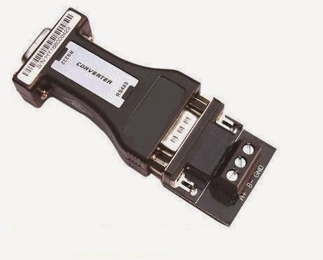
RS422, RS485, comparison with RS232

RS232 is well-known due to popularity of today’s PC’s, unlike the RS422 and RS485. These are used in industry for control systems and data transfers (small volumes, less than hundreds of Mb/s).
So, what is the main difference between RS 232 and RS 422 & 485? The RS 232 signals are represented by voltage levels with respect to ground.

There is a wire for each signal, together with the ground signal (reference for voltage levels). This interface is useful for point-to-point communication at slow speeds. For example, port COM1 in a PC can be used for a mouse, port COM2 for a modem, etc. This is an example of point-to-point communication: one port, one device. Due to the way the signals are connected, a common ground is required. This implies limited cable length? About 30 to 60 meters maximum. (Main problems are interference and resistance of the cable.) Shortly, RS 232 was designed for communication of local devices, and supports one transmitter and one receiver.
RS422 & 485 uses a different principle: Each signal uses one twisted pair (TP) line-two wires twisted around themselves. We’re talking ‘Balanced data transmission’, or ‘Differential voltage transmission’. Simply, let’s label one of the TP wires ‘A’ and the other one ‘B’. Then, the signal is inactive when the voltage at A is negative and the voltage at B is positive. Otherwise, the signal is active, A is positive and B is negative. Of course, the difference between the wires A and B matters. For RS 422 & 485 the cable can be up to 1200 meters (4000 feet) long, and commonly available circuits work at 2.5 MB/s transfer rate.
What is the difference between RS 422 and RS 485? Electrical principle is the same both use differential transmitters with alternating voltages 0 and 5V. However, RS is intended for point-to-point communications, like RS 232. RS 422 is intended uses two separate TP wires, data can be transferred in both directions simultaneously. RS 422 is often used to extend a RS 232 line, or in industrial environments.
RS 485 is used for multiply-point communications: more devices may be connected to a single cable- similar to e.g ETHERNET networks, which use coaxial cable. Most RS 485 systems use Master/Slave architecture, where each slave unit has its unique address and responds only to packets addressed to this unit. These packets are generated by Master (e.g PC), which periodically polls all connected salve units.

Quick Comparison Chart: