CCTV system design
Designing a CCTV system is a complex task,
requiring at least basic knowledge of all the stages in a system, as well as
its components. But more importantly, prior to designing the system, we need to
know what the customer expects from it.
Understanding the customer’s requirements
The first and most important preparation
before commencing the design is to know and understand the customer’s
requirements. Customers can be technically oriented people, and many understand
CCTV as well as you do, but most often they are not aware of the latest
technical developments and capabilities of each component.
The most important thing to understand is the
general concept of the surveillance the customer wants, Constant monitoring of
cameras and activities undertaken by 24-hour security personnel, or perhaps
just an unattended operation (usually with constant recording), or maybe a
mixture of the two. Once you understand their general requirements, it might be
a good idea to explain to them what is achievable with the equipment you would
be suggesting. This is reasonably easy to accomplish with smaller and simpler
systems, but once they grow to a size of more than 10 cameras some of which
could be PTZs, a few monitors, more than one control point, a
number of alarms, VCRs, and the like, things will get tougher.
Many unknown variables need to be considered:
What happens if a number of alarms go off simultaneously? Which monitor should
display the alarms? Will the alarms be recorded if the DVR/VCR(s) is/are playing
back? What is the level of priority for each operator? And so on.
Those are the variables that define the system
complexity and as in mathematics, in order to solve a system with more
variables, one needs to know more parameters. They can be specified by the
customer, but only after the customer has understood the technical capabilities
of the equipment.
Understandably, it is imperative for you, as a
CCTV expert, to know the components, hardware, and software you would be
offering and to achieve what is required in the best possible way. You can
create a favorable impression in the customer’s mind if at the end you give him
or her as much as, or even more than, what you have promised. You will prove unsatisfactory
if you do not. Remember that if the customer is fully satisfied the first time,
chances are he or she will come back to do business with you again. To put it
simply: Do not claim the system will do this and that if you are not certain;
make sure your system delivers what you say it will.
So, to design a good, functional system, one
has to know the components used, their benefits and limitations, how they
interconnect, and how the customer wants them to be used. The first few parts are assumed to be
fulfilled, since you would not be doing that job unless you knew a few things
about CCTV. The last one – what the customer wants – can be determined during the
first phone call or meeting.
Usually, the next step is to conduct a site
inspection. Here is a short list of questions you should ask your customer
prior to designing the system and before or during the site inspection:
• What is the main purpose
of the CCTV system?
If it is a deterrent, you need to plan for cameras and
monitors that will be displayed to the public.
If it is a concealed surveillance, you will need to pay
special attention to the camera type and size, its protection, concealed cabling, and the like, as
well as when it is supposed to be installed (after hours perhaps).
• Who will be the
operator(s) ?
If a dedicated 24 hour guard is going to use the system,
the alarm response needs to be different from that expected when unattended, or a partially
attended, system operation.
• Will it be a monochrome
or color system ?
The answer to this question will dictate the price, as
well as the minimum illumination response.
Consequently, the lighting in the area needs to be looked
at. A color picture will give more details about the observed events, but if
the intention is to see images in very low light levels, or with infrared
lights, there is no other alternative but B/W cameras (unless the customer is
prepared to pay for some of the new cameras available on the market that switch
between color and monochrome operation).
The price of a color system is dictated not only by the
cameras, but also by the monitors, multiplexers, and/or quads (if any).
Needless to say, sequential or matrix switchers, as well as time-lapse VCRs,
are the same for both B/W and color.
• How many cameras are to
be used ?
A small system with up to half a dozen cameras can be
easily handled by a switcher or multiplexer, but bigger systems usually need a matrix switcher or a larger
number of switchers and multiplexers.
• How many of the cameras
will be fixed focal length and how many PTZ ?
There is a big difference in price between the two
because if a PTZ camera is used instead of a fixed one, the extra cost is in
the zoom lens (as opposed to the fixed one), the pan and tilt head or dome, the
site driver, and the control keyboard to control it. But the advantages your
customer will get having a PTZ camera will be quadrupled. If on top of this,
preset positioning PTZ cameras are used, the system flexibility and efficiency
will be too great to be compared with the fixed camera system. A system with only
one PTZ camera and half a dozen fixed ones is a choice that may require a
matrix switcher for control and will increase the price dramatically (compared
to a system with only fixed cameras). Alternatively, single PTZ camera control
can be achieved via a special single-camera digital or hard-wired controller,
but they would also increase the price considerably. So, if a PTZ camera is
required, it would be more economical to have more than one PTZ camera.
• How many monitors and
control keyboards are required?
If it is a small system, one monitor and keyboard is the
logical proposal, but once you get more operators and/or channels to control
and view simultaneously, it becomes harder to plan a practical and efficient system. Then, an inspection of the control
room is necessary in order to plan the equipment layout and interconnection.
• Will the system be used
for live monitoring (which will require an instant response to alarms), or
perhaps recording of the signals for later review and verification ?
This question will define whether you need to use DVR/VCR(s)
with multiplexer(s). If you have a matrix switcher, you will still need a
multiplexer or two in addition. Have in mind that the time lapse mode you are
going to use depends on how often the tapes can be changed, and this defines the
update rate of each camera recorded. Choose, whenever possible, a pair of 9-way
(or 8-way) multiplexers instead of one 16-way, if you want to minimize the time
delay in the recording rate update.
• What transmission media
can be used on the premises ?
Usually, a coaxial cable is taken as an unwritten rule
and installation should be planned accordingly. Sometimes, however, there is no
choice but to use a wireless microwave or even a fiber optics transmission,
which will add considerably to the total price. If the premises are subject to
regular
lightning activity, you had better propose fiber optics
from the beginning and explain to the customer the savings in the long run. So,
you have to find out more about the environment in which the system is going,
what is physically possible and what is not, and then plan an adequate video
and data transmission media.
• Lastly and probably the
most important thing to find out, if possible, is what sort of budget is
planned for such a CCTV system?
This question will define and clarify some of the
previous queries and will force you to narrow down either the type of
equipment, the number of cameras, or how the system is expected to work.
Although this is one of the most important factors, it should not force you to
downgrade the system to something that you know will not operate
satisfactorily.
If the budget cannot allow for the desired system, it is
still good to go back to the customer with a system proposal that you are
convinced will work as per his or her requirements (even if it is over budget)
and another one designed within the budget with as many features as the budget
will allow for. This will usually force you to narrow down the number of
cameras, or change some from PTZ to fixed. The strongest argument you should
put forward when suggesting your design is that a CCTV system should be a
secure one, which can only be the case if it is done properly. Thus, by having
a well-designed system, bigger savings will be made in the long run.
By presenting a fair and detailed explanation of how you
think the system should work, the customer will usually accept the proposal.
Site inspections
After the initial conversation with the customer and
assuming you have a reasonably good idea of what is desired, you have to make a
site inspection where you would usually collect the following information:
• Cameras: type (i.e., B/W or color, fixed or PTZ, Resolution, etc.).
• Lenses: angles of view, zoom magnification ratio for
zoom lenses (12.5–75 mm, 8–80 mm, etc.).
• Camera protection: housing type (standard, weatherproof,
dome, discrete, etc.) mounting.
• Light: levels, light sources in use (especially when
color cameras are to be used), east/west viewing direction. Visualize the sun’s
position during various days of the year, both summer and winter. This will be
very important for overall picture quality.
• Video receiving equipment: location, control room area,
physical space, and the console.
• Monitors: Resolution, size, position, mounting, and the
like.
• Power supply: type, size (always consider more amperes
than what are required). Is there a need for an uninterruptable power supply
(UPS)? (VA rating in that case).
• If pan/tilt heads are to be used: type, size, load
rating, control (two wire – digital or multi-core). Is there a need for preset
positioning (highly recommended for bigger systems)? Where are they going to be
mounted? What type of brackets ?
• Make a rough sketch of the area, with the approximate
initial suggestions for the camera positions. Take into account, as much as
possible, the installer’s point of view. A small change in the camera’s
position, which will not affect the camera’s customer. An unwritten golden rule
for a good picture is to try and keep the camera from directly facing light.
• Put down the reference names of areas where the
customer wants (or where you have suggested) the cameras to be installed. Also
write down the reference names of areas to be monitored because you will need
them in your documentation as reference points. Be alert for obvious “no-nos” (in
respect to installation), even if the customer wishes something to be done.
Sometimes small changes may result in high installation costs or technical
difficulties that would be impossible to solve. It is always easier to deter
the customer from making changes by explaining why in the initial stage, rather
than having to do so later in the course of installation, when additional costs
will be unavoidable.
To know more just read Condensed Code BS EN 62676-4 and BS EN 50132-7, BS EN 62676-4 Clause 4.4 & BS EN 62676-4 Clause 4.5.
Designing and quoting a CCTV system
With all of the above information, as well as the product
knowledge (which needs constant updating), you need to sit down and think.
Designing a system, like designing anything new, is a
form of art. As is true of many artists, your work may not be rewarded
immediately, or it may not be accepted for some reason. But think positively
and concentrate as if that is to be the best system you can propose. With a
little bit of luck you may make it the best, and tomorrow you can proudly show it to your
colleagues and customers. Different people will use different methods when
designing a system. There is, however, an easy and logical beginning.
Always start with a
hand drawing of what you think the system should feature. Draw the
monitors, cameras, housings, interconnecting cables, power supplies, and so on.
While drawing you will see the physical interconnection and component
requirements. Then you will not omit any of the little things
that can sometimes be forgotten, such as camera brackets,
types of cable used, and cable length. Making even a rough hand sketch will
bring you to some corrections, improvements, or perhaps further inquiries to
the customer. You may, for example, have forgotten to check what the maximum
distance for the PTZ control is, or how far the operators are to be from the
central video processing equipment, power cable distances, voltage drops, and
so on.
Once you have made the final hand drawing, you will know
what equipment is required, and it is at this point that you can make a listing of the proposed equipment. Then, perhaps, you will
come to
the stage of matching camera/lens combinations. Make sure
that they will fit in the housings or domes you intend to use. This is another chance to glance
through the supplier’s specifications booklet. Do not forget to take into
account some trivial things that may make installation difficult, like the
coaxial cable space behind the camera (remember, it is always good to have at
least 50 mm for BNC terminations), the focusing movement of a zoom lens (as
mentioned earlier in the chapter on zoom lenses, in a lot of zoom lenses
focusing near makes the front optical element protrude for an additional couple
of millimeters), and so on.
The next stage is pricing the equipment – costs, sales
tax and duty, installation costs, profit margins and the most important of all
(especially for the customer) the total price.
Do not forget to include commissioning costs in there,
although a lot of people break that up and show the commissioning figure
separately. This is more of a practical matter, since the commissioning cost may vary considerably and it could take longer or shorter
than planned. General practical experience shows that it will always take at least three times
longer than planned. Also, in the commissioning fees, time should be allocated for the CCTV operator’s
training.
After this step has been completed, you need to make a
final and more accurate drawing of the system you are proposing. This can be hand drawn, but most CCTV
designers these days use computers and CAD programs. It is easier and quicker (once you get used
to it), and it looks better.
Also, the hand-calculated price needs to be written in a
quotation form, with a basic explanation of how the system will work and what it will achieve. It is
important for this to be written in a concise and simple, yet precise form, because quotations and
proposals (besides being read by security managers and technical people) are
also read by nontechnical people such as purchasing officers and accountants.
Often, spreadsheet programs are used for the purpose of
precise calculation, and this is another chance to double-check the equipment listing with your drawing
and make sure nothing has been left out. As with any quotation, it is more professional to have a
set of brochures enclosed for the components you are proposing.
In the quotation, you should not forget to include your
company’s terms and conditions of sale which will protect your legal position.
If the quotation is a response to a tender invitation, you
will most likely need to submit a statement of compliance.
This is where you confirm whether your equipment complies
or does not comply with the tender requirements. This is where you also have to
highlight eventual extra benefits and features your equipment offers. In the
tender, you may also be asked to commit yourself to the progress of the work and supply work insurance cover, in which case you will
need a little bit of help from your accountant and/or legal advisor.
Many specialized companies only design and supply CCTV
equipment, in which case you will need to get a quote from a specialized installer, who,
understandably, will need to inspect the site. It is a good practice, at the
end, to have all the text, drawings, and brochures bound in a single document,
in a few copies, so as to be practical and efficient for reviewing and
discussions.
Installation considerations
If you are a CCTV system designer, you do not have to
worry about how certain cables will be pulled through a ceiling, raisers, or camera
pole mounting; that is the installer’s job. But it would be very helpful and
will save a lot of money, if you have some knowledge in that area. If nothing
else, it is a good practice, before you prepare the final quotation, to
take your preferred installer on site, so that you can take into account his or
her comments and suggestions of how the practical installation should be
carried out.
First, the most important thing to consider is the type
of cable to be used for video, power, and data transmission, their distances and
protection from mechanical damage, electromagnetic radiation, ultraviolet
protection, rain, salty air, and the like. For this purpose it is handy to know
the surrounding area, especially if you have powerful electrical machinery next
door, which consumes a lot of current and could possibly affect the video and
control signals. Powerful electric motors that start and stop often may produce
a very strong electromagnetic field and may even affect the phase stability of
the mains. This in turn will affect the camera synchronization (if line-locked
cameras are used) as well as the monitor’s picture display.
For example, there might be a radio antenna installed in
the vicinity, whose radiation harmonics may influence the highfrequency signals
your CCTV system uses.
Mounting considerations are also important at both the
camera and monitor end. If poles are to be installed, not only the height, but
also the elasticity of the poles is important. Steel poles, for example, are
much more elastic than concrete poles. If a PTZ camera is installed, the zoom
lens magnification factor will also magnify the pole’s movement which could
result from wind, or vibrations from the pan/tilt head movement itself. This magnification
factor is the same as the optical magnification (i.e., a zoom lens, when fully
zoomed in, may magnify a 1mm movement of the camera due to wind to a 1 m
variation at the object plane).
The shape of the pole is also very important
– hexagonal poles are less elastic than round ones of the
same height and diameter.
The same logic applies to camera and pan/tilt head
mounting brackets. A very cheap bracket of a bad design can cause an unstable
and oscillating picture from even the best camera.
If the system needs to be installed in a prestigious hotel
or shopping center, the aesthetics are an additional factor to determine the
type of brackets and mounting. It is especially important then not to have any
cables hanging.
The monitoring end demands attention to all aspects. It
needs to be durable (people will be working with the equipment day and night),
or aesthetical (it should look good) and practical (easy to see pictures,
without getting tired of too much noise and flashing screens).
Since all of the cables used in a system wind up at the
monitoring end and in most cases this is the same room where the equipment is
located, special attention needs to be paid to cable arrangement and
protection.
Often, cables lying around on the floor for a few days
(during the installation) are subject to people walking on them, which is
enough weight to damage the cable characteristics, especially the coaxial cable
impedance. Remember, the impedance depends on the physical relation between the
center core, the insulation, and the shield. If a bigger system is in question,
it is always a better idea to propose a raised floor, where all the cables are
installed freely below the raised floor.
Sometimes, if a raised floor is not possible, many cables
can be run over a false ceiling. In such cases special care should be taken to secure
the cables as they could become very heavy when bundled together.
Larger installations may want a patch panel for the video
signals.
This is usually housed in a 19'' rack cabinet, and its
purpose is to break the cables with special coax link connectors so as to be
able to reroute them in case of a problem or testing.
Many installers fail to get into the habit of marking the
cables properly. Most of them would know all of the cables at the time of
installation, but two days later they can easily forget them. Cable marking is
especially critical with larger and more complex systems. Insist on proper and
permanent cable markings as per your drawings. There are plenty of special
cable-marking systems on the market. In addition, listing of all the numbers
used on the cables should be prepared and added to the system drawings.
Remember, good installers differ from bad ones in the way
they terminate, run, arrange, and mark the cables, as well as how they document
their work.
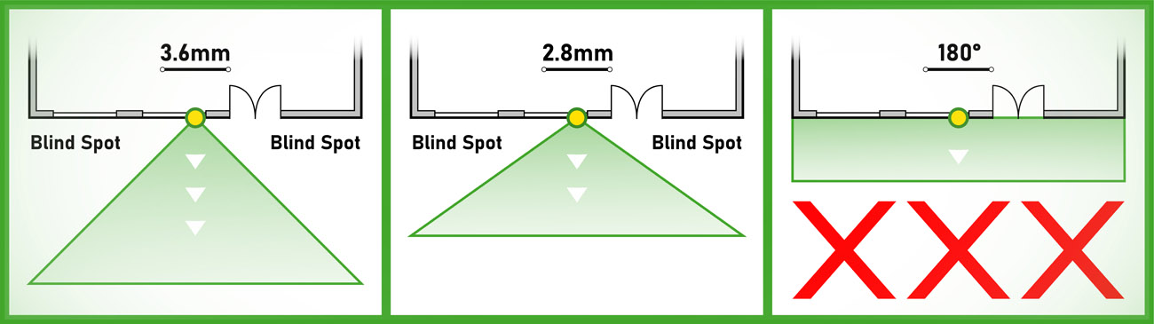
Mid Wall Pattern
Mounting a camera mid wall and adjusting its view perpendicular to the wall. This location can be useful for certain applications but is seldom used by security professionals, simply because it creates a blind spot on each side of the camera. A 3.6mm lens provides the widest viewing angle without distorting the image. There are 180 degree cameras on the market but they distort the video so badly that the video is useless at distance. We do not recommend using any lens wider than a 2.8mm, which provides a viewing angle of 110 degrees. Still, with such a wide viewing angle, do not expect great clarity beyond 40 feet (there is a warping or bubble effect past 40 feet). Because of this, a 2.8mm lens should be used for up close applications - such as a porch or any location where you desire a very wide angle view but do not require great detail at distance.
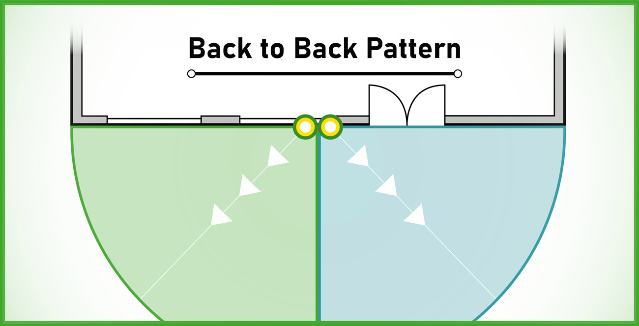
Back to Back Pattern
Place two cameras back to back mid wall. This design eliminates the blind spots that can occur when using one camera mid wall.
Secret Service Pattern
Two cameras are installed on the same wall, separated by 15-20 feet and aimed towards each other. Basically, the cameras are watching each other’s back so that neither camera can be disabled without the perpetrator being seen. This design works well with both fixed view and zoom lens cameras.
Corner to Corner
This design is the most common and provides several benefits. It makes the most of each camera's viewing capability and covers 100% of the perimeter. When the cameras are placed as the diagram below indicates, all blind spots are eliminated and the cameras cannot be vandalized without the perpetrator being recorded by another camera.
Inside Corner
This pattern is simple and very effective. Because a 3.6mm lens provides a 90 degree field of view, it is perfect for an inside corner. When using this method, the camera cannot be vandalized and the corner is covered wall to wall.
Drawings
There is no standard for drawing CCTV system block
diagrams, as there is in electronics or architecture. Any clear drawing should
be acceptable as long as you have clearly shown the equipment used (i.e.,
cameras, monitors, VCRs) and their interconnection.
Many people use technical drawing aids, such as CAD
programs, or other PC or Mac-based drawing packages. Depending on the system
size, it might be necessary to have two different types of drawings: one of a
CCTV block diagram showing the CCTV components’ interconnection and cabling requirements,
while the other could be a site layout with the camera positions and coverage
area. In smaller installations, just a block diagram may be sufficient.
The CCTV block diagram needs to show the system in its
completeness, how the components are interconnected, which part goes where,
what type of cable is used, and where it is used.
If the site layout drawing is well prepared, it can later
be used as a reference by the installer, as well as by your customer and yourself
when reviewing camera locations, reference names, and discussing eventual
changes.
When the CCTV system is installed and the job is
finished, drawings may need small alterations, depending on the changes made
during the installation. After the installation, the drawings are usually enclosed
with the final documentation, which should also include manuals, brochures, and
other relevant documentation.
Commissioning
Commissioning is the last and most important procedure in
a CCTV system design before handing it over to the customer. It involves great
knowledge and understanding of both the customer’s requirements and the system’s
possibilities. Quite often, CCTV equipment programming and setup are also part
of this. It includes video matrix switcher programming, time-lapse VCR
programming, camera setup, and so on.
Commissioning is usually conducted in close cooperation
with the customer’s system manager and/or operator(s), since a lot of settings
and details are made to suit their work environment.
The following is a typical list of what is usually
checked when commissioning:
All wiring is correctly terminated.
Supply voltage is correct to all appropriate parts of the
system.
Camera type and lens fitted are correct for each
position.
Operation of auto irises under various light levels is
satisfactory.
If VCRs are fitted, they should be recording in the most
efficient time-lapse mode (especially when multiplexed cameras are being
recorded).
If DVRs are installed, the pictures per second
performance and image quality (compression setting) should be checked .
All system controls are properly functioning (pan/tilt,
zoom, focus, etc.)
The setting of all pan and tilt limits is correct.
Preset positioning, if such cameras are used, is correct.
The level of supplementary lighting is satisfactory.
The system must continue to work when the main supply is disconnected,
and a check should be made as to how long it does (if UPS is used).
Commissioning larger systems may take a bit longer than
the smaller ones. This is an evolution from the system on paper to the real
thing, where a lot of small and unplanned things may come up because of new
variations in the system concept. Customers, or users, can suggest the way they
want things to be done, only when they see the initial system appearance.
Commissioning in such cases may therefore take up to a few days.
Commissioning under BS EN 62676-4 Clause 4.6 & BS EN 62676-4 Clause 13.
Training and manuals
After the initial setup, programming, and commissioning
are finished, the operators, or system users, will need some form of training.
For smaller systems this is fairly straightforward and
simple. Just a verbal explanation may be sufficient, although every customer
deserves a written user’s manual. This can be as simple as a laminated sheet of
paper with clearly written instructions.
Every piece of equipment should come with its own User’s
Manual, be it a time lapse VCR, a camera, or a switcher, but they have to be
put together in a system with all their interconnections and this is what has
to be shown to the customer. Every detail should be covered, especially alarm
response and the system’s handling in such cases. This is perhaps the most
important piece of information to the operators.
For larger systems, it is a good idea to bind all the component
manuals, together with the system drawings, wiring details, and operator’s instructions,
in a separate folder or a binder. Naturally, for systems of a larger size, training
can be a more complex task. It may even require some special presentation with
slides and drawings so as to cover all the major aspects.
Good systems are recognized not only by their
functionality but also by their documentation.
Handing over
When all is finished and the customer is comfortable with
what he or she is getting, it is time to hand over the system. This is an official
acceptance of the system as demonstrated and is usually backed by the signing
of appropriate documents.
It is at this point in time that the job can be
considered finished and the warranty begins to be effective.
From now on, the customer takes over responsibility for
the system’s integrity and operation.
If customers are happy with the job, they usually write
an official note of thanks. This may be used later, together with your other
similar letters, as a reference for future customers.
Documentation consider BS EN 62676-4 Clause 4.8, BS EN 62676-4 Clause 15.3 & BS EN 62676-4 Clause 16.
Preventative maintenance
Effective and regular maintenance of a CCTV surveillance
system is essential to ensure that the system remains reliable at all times. It
is advisable that maintenance of the CCTV system should be carried out by the
company which installed the system. However, the maintenance company should
have the means, including necessary spare parts and documentation, to meet the
recommendations given here.
Note: This recommendation does not place an obligation
upon customers who purchase their systems to have them maintained by the
installing company. Maintenance is a matter of agreement between the customer
and the installing company or a separate maintenance company. Maintenance comes
under BS EN 62676-4 Clause 17 & SC CoP Guiding Principle 10.
The preservation of security within the maintenance
company is of paramount importance and steps should be taken to ensure the safe
keeping of all customers’ equipment and documentation relating to a particular
installation/contract.
Note: BS EN 50132-7 states that “CCTV systems should be
maintained in accordance with the schedule supplied by the system designer or
supplier”, but does not detail any specific maintenance requirements. These
guidelines give specific advice for the maintenance of CCTV surveillance
systems, and provide examples of the type of documentation required to be used
by the service company.
A maintenance company should ensure that adequate vetting
of all employees is carried out. All employees, who visit a customer’s
premises, shall carry identification cards which should include a photograph
and signature of the bearer, the company’s name, contact details and a date of
expiry (maximum of 3 years).
Each service technician employed by the maintenance
company should carry a range of tools, test equipment and other equipment to
enable them to perform their functions satisfactorily. Specialist tools, test
equipment and plant should be available for deeper investigation if necessary.
Note: Disconnections, for whatever reason, should be
recorded on a maintenance record and authorised by the client or his
representative.
The maintenance company’s organisation should be so
staffed as to ensure that the recommendations of this Code of Practice can be
met at all times. The following factors should be taken into consideration:
1.
the number of installations to be serviced
2.
the complexity of the installations;
3.
the geographical spread of the installations in
relation to the location of the maintenance company, its branches and its
service personnel
4.
the method of calling out service personnel
outside normal office hours, where applicable.
5.
Service personnel should be adequately trained
and training should be updated whenever appropriate.
Maintenance Service is 3 types but scope of work is same.
A. Preventive Maintenance service.
B. Corrective Maintenance service.
C. Performance Maintenance service.
http://arindamcctvaccesscontrol.blogspot.in/2014/09/service-and-maintenance-for-cctv.html
Note: The BS EN standards BS EN 62676-2-X comprising part 1, 2 and 3, provide detailed guidelines to manufacturers as to how they should implement IP video transmission products.
An end user is unlikely to benefit by reading the 62676-2-X standards. They may instead be involved in a buying decision which could place reliance on claims of conformance to the part of the BS EN standard the manufacturer chose to implement. Interoperability of equipment is not solely reliant on the requirements included in the BS EN standards in their current form. There is no guarantee that a product which simply claims BS EN 62676 compliance will provide full compatibility with another claiming the same compliance although it should allow for a minimum level of image transfer.
Installers, users and specifiers should treat claims of interoperability between manufacturers products with caution. The parts of the BS EN standard which focus on interoperability, are 62676-2-2, which describes the PSIA guidelines for interoperability of IP Video devices, and 62676-2-3, which describes the ONVIF guidelines for interoperability.
ONVIF and PSIA, are at their base level, a common set of commands allowing basic communication between devices but this does not guarantee that the devices will function to the full potential of their design. Issues with product firmware and software should also be considered: a change of firmware / software versions should be tested separately to ensure continued interoperability. Whilst the specifications try to take this into account, the number of products claiming to be conformant currently makes this an impossible task.
Claims by product manufacturers that PSIA or ONVIF compliance means that users do not have to check that the products work together should be treated with great caution. It is strongly recommended that all such products are tested before being deployed.