Showing posts with label HID Reader. Show all posts

Wednesday, February 1, 2023

Access Control Commissioning Checklist

Access Control Commissioning Checklist 

All customers are not knowledgeable to understand Access control system. When we are getting order it’s our responsibility to commissioned in proper way. In India maximum system integrator do not follow their own check list and as a result after few month call logging is started. Some call forward to OEM and System Integrator with customer’s blame on products are not good. But no one drilldown about commissioning report. Ultimately system integrator don’t know commissioning also a part of BOQ, yes they put importance only installation. I hope this checklist helps end users, integrators and consultants verify that access control installation and commissioning is complete. Take print edit as per your projects and fill all point. After that attached this with handover documents.

It covers the following sections:

  • Door Hardware Checks
  • Reader Checks
  • Controller Checks
  • Fire Alarm Loop Confirmation
  • Backup Power Compliance
  • RTE and 'Free Egress' Confirmation
  • Door Timing Checks
  • Turnstiles or Gate/Door Operator Checks
  • Credential Enrolment
  • Credential Issuance
  • Database Migration
  • Management Software User Creation
  • Access Levels and Schedules
  • Access Event Notifications
  • Door Held Open / Forced Open Troubleshooting
  • Anti-Passback Troubleshooting
  • Mapping and Custom Reporting Creation
  • Viewing Clients Installation 
  • Integration with VMS and Other Systems
  • Workstation Setup
  • Network Setup
  • Cable Verification

We recommend each person using this customize the list for their own needs / situations. There is no 'one size fits all' checklist but this list is meant to serve as a starting point to make it easier and quicker to build your own.

Door Locks and Hardware

This section covers commissioning of doors and opening locks, strikes, or other electro-mechanical hardware, including mounting and physical considerations.

Physical Operation, For every controlled opening:

  • Check all lock / hardware fasteners or mounts are secure and without play, slack, or gaps exceeding tolerances on installation instructions.
  • Ensure operation of lock is free of binding, grinding, or interference for door or frame features or other components.
  • Close and open door, or operate several cycles, the opening to ensure that no binding or warping is affecting operation. 
  • If Exit Devices are used, confirm appropriate 'Push to Exit' signage is displayed.
  • If Door Closers or Operators are used, confirm electronic access devices do not interfere with operation.
  • Confirm secure installation and function of Door Position Switches/ Contacts/ DPS.
  • Weatherproof and lightly apply grease per specification to mechanical hardware like hinges
  • Ensure any cabling or system wiring is hidden, tucked behind raceway or frames, and is not being pinched or cut by features like hinges.
  • Confirm that accessibility clearances are satisfied and any additional access control devices comply with codes.
  • If standalone, battery powered locks are used, confirm remaining battery life is strong and document commission date of batteries for future reference.

Door Controller Install Checks

  • Confirm that all terminated wiring at controller is secured and terminated without short for each device.
  • If kept in a metal enclosure, ensure panel tamper contacts and panel locks are used.  Gather panel keys for central, secure management.
  • If controllers are located at the door, confirm they are installed on the secure/locked side of the opening and located behind a tamper-resistant or semi-obscured location, such as above tiles at the door.
  • For wireless locks, confirm that all hubs or repeaters are clearly labeled as companions to the separate system readers or controllers.

Free Egress and Fire Alarm Loop Check

  • Confirm that upon fire alarm activation, all door maglocks release and are not powered.
  • Confirm that upon fire alarm activation, all emergency exit doors and openings can be freely opened and are not locked for any reason.
  • Confirm that during normal operating conditions, all 'Request To Exit' devices are located in code compliant arrangements and function properly.
  • Check that any delayed egress openings have specifically been approved by the AHJ, and delays do not exceed 15 seconds, unless specifically excepted by AHJ.
  • Confirm that all Pushbutton style RTE switches are properly labeled and displayed per local code requirements, and directly interrupt power to locks and not controller, unless specifically excepted by AHJ.

Credential Reader Checks

  • Confirm that reader device is securely anchored without gaps to the wall, frame, post, or bollard.  Seal or install trim guards where needed.
  • Confirm 'normal operation' status lights are displayed per intended behavior. (On/Off/Red/Green/Blue, etc.)
  • Confirm audible beep or siren registers when credential is read.
  • Check that reader tamper device is connected and configured.
  • If contactless type reader, present test card to confirm read range meets spec.  
  • If biometric type reader, confirm unit positioning will not be interfered with by environmental features (ie: sun movement, HVAC downdrafts, etc)
  • Confirm that accessibility clearances are satisfied and any additional access control devices comply with codes.

Credential Enrolment

  • Confirm that the only credentials to be immediately carried/used by cardholders are activated, and no batched activation of unissued/ stored credentials is done.
  • Check that each user issued a credential is accurately classified and identified in the access control software.  Include Picture ID images if possible.
  • If credentials are being renewed or exchanged, confirm physical possession, disposal, and deactivation of old credential in system.
  • If biometric credentials are enrolled, confirm multiple digits or templates are enrolled.
  • If multi-factor credentials are issued, confirm that all factors are recorded, active, and valid in the system.

Access Management Software Servers

This section covers commissioning of Management Software servers and appliances, including both hardware/network setup as well as OS and software. Some of these items may not be used depending on OS and access platform. For example, appliances typically do not require OS updates. OEM to OEM process are slight different.

Access Management Software Configuration

  • Configure Unlock, Extended unlock, Door Hold Open, and Relock event periods, as appropriate.
  • Configure user access schedules (e.g., 24/7, 8am-5pm, off-hours, holidays, etc.)
  • Configure user access levels (e.g., Managers, Workers, Visitors, Temporaries, etc.)
  • Confirm Polling Interval, or settings update push duration as prompt and as close to real-time to be accurate as recorded in system.
  • Configure any Maps or floorplans used to display and manage system control points.
  • Confirm successful integration and configuration of features like 'Video Verification', or integration with video surveillance, intrusion, fire alarm, and intercom systems.
  • Configure alarm or event notifications (email, text, etc.)
  • Download and retain copies of all door/controller configurations
  • Confirm any imported databases are clean and without problems if populating access management system.
  • For 'Anti-Passback' rules, ensure that users will not unwittingly or inadvertently cause alarms if they use atypical or uncontrolled openings.

Hardware/Security

  • Document MAC address(es) (often more than one if using multiple network cards), or if hosted/cloud access is used, document hostnames of all remote servers.
  • Assign and document IP address(es) of every networked device, endpoint, or server.
  • Apply latest OS updates (unless not recommended by manufacturer);
  • Create secure admin password
  • Create additional users as specified
  • Test UPS operation and runtime (if supplied);

Network/Security Settings

  • Document Controller and other ethernet-based devices MAC address;
  • Assign and document Controller and other ethernet-based device IP address
  • Update firmware to latest version (or manufacturer recommended/tested if different)
  • Change Controller admin password from default
  • Create multiple users if required (by specification or manufacturer recommendation)
  • Set NTP server and verify time and date;
  • Disable unused services/close unused ports (FTP, telnet, SSH, etc.);

General Server Settings

  • Confirm any requisite services or policies are free to operate and will restore automatically after reboot events.
  • Change access management admin password from default
  • Create operator/user logins
  • If LDAP or Active Directory is used, confirm valid implementation and provisioning of service.
  • Confirm and document any external database connections or dependencies by the access software.

Workstations

This list involves client workstations, including hardware, OS, and access client setup and commissioning. Some of these steps may be omitted if appliances are used. OEM to OEM process are slight different.

  • Document MAC address(es) of each workstation
  • Assign and document IP address(es)
  • Apply latest OS updates (unless not recommended by manufacturer)
  • Create secure admin password
  • Create additional users as specified
  • If dongles or hardware keys are required for client access, document location of key on workstation (e.g., Port Location, Key Serial Number)

Network

This section outlines commissioning of network hardware, including switches, routers, firewalls, etc. Some of these devices may not be used in all systems, or managed by the installing integrator.

  • Document MAC address(es) of each device
  • Assign IP address and document
  • Update switch/firewall/router firmware to latest version
  • Change admin password from default
  • Configure VLAN(s) as required; 
  • Configure QoS as required;
  • Disable unused switch ports as specified
  • Configure SNMP monitoring if required;
  • Configure MAC filtering if required
  • Download and retain configuration for each switch
  • Test UPS operation and runtime for each endpoint, if supplied
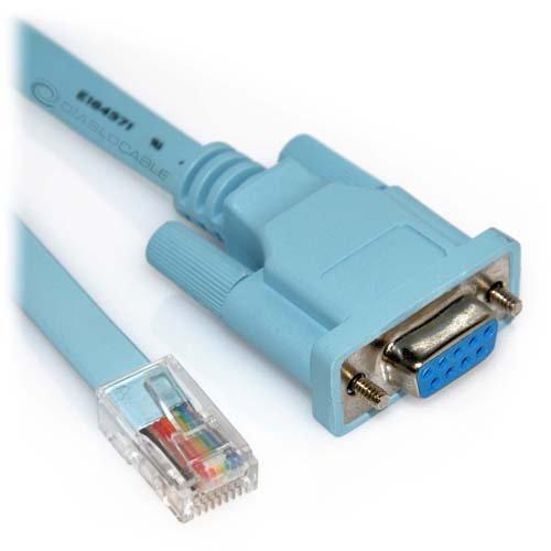
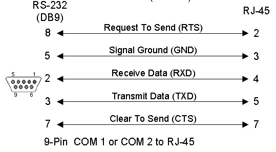
Cabling

This section covers commissioning of the access control cabling system, including labeling, supports, aesthetic concerns, and testing. OEM to OEM process are slight different.

  • Label all cables, patch panels, wall outlets, etc., as specified
  • Ensure cables are secured to supports (J-hooks, ceiling truss, etc.)
  • Conceal cables where possible/required
  • Leave properly coiled and dressed service loops at Controller or Switch location and head end as required;
  • Test all terminations and document results as specified
  • Document cable test results as specified (if certification is required)


 If need any expert comment on your projects we can help you free of cost over voice or text.


Friday, August 5, 2016

Facility Code or Site Code

What is a Facility Code ?
There are many different proximity card formats, but the proximity cards that we sell are encoded with a "Standard" 26-Bit Wiegand format.  Like other proximity and RFID cards, an HID card is simply an ID card which enables proximity technology in its everyday functions. HID cards, as well as other types of RFID cards and smart cards, are popular for access control, as well as other functions like public transportation and employee ID.This format actually contains two sets of numbers:
  •         A 3-digit "facility code", which can range from 1-255
  •         A 5-digit "card number", which can range from 1-65,535.

Most HID proximity cards and key fobs have the 5-digit card number printed on the card.  The 3-digit facility code, however, is printed only on the box in which your cards are shipped.
Gate Keeper can be configured to interpret the Wigand data as either a 16-bit number or a 24-bit number.  The 16-bit number will contain only the 5-digit card number.  The 24-bit number will contain the facility code and card number for a total of 8 digits.  For example, if the facility code for a card is "123" and the card number is "56789" then the 24-bit (8-digit) number read from the card will be "12356789".
A Facility Code is a number encoded on access cards that is intended to represent a specific protected facility or building. Not all card formats support a Facility Code, but the most common card data format in use today does support it — the industry’s original open (i.e. non-proprietary) 26-bit format. The 26-bit format has two data fields: a Facility Code (8 bits) and a Card Number (16 bits), plus two parity bits; thus, the Facility Code number can be a number be between 0 and 255, and the Card Number can be between 0 and 65,535.
With only 65,535 card numbers available across the cards of all customers using the 26-bit card data format, duplicate card numbers are inevitable; therefore, the first purpose of the Facility Code was to enable customers in close proximity to each other to differentiate their set of cards from another customer’s cards. Ideally, each manufacturer would try to manage the facility numbers it issued to various customers in a specific area to minimize the occurrence of duplicates. A card with a Facility Code not matching those used by that specific customer would be denied access, typically generating “Access Denied – Wrong Facility Code” messages.
The 26 bit Wiegand standard format is the industry standard. Card manufacturers such as HID, Indala and AWID sell cards with this format to any dealer. This 26 bit format is recognized by all access hardware.

Over the years, formats with a higher number of bits (33, 37, 48, 50)  have been added to increase card security.


However, some of the higher bit formats are  "proprietary", and usually carry a higher price tag. One exception is the HID 37 bit proprietary format, priced similarly to a 26 bit card.


As an example, if Company A has cards numbered from 1 to 1000, with facility code 230, they would be programmed as follows:

230 - 00001

230 - 00002
230 - 00003 .......up to 230 - 01000

Company B could have the same serial numbers, but with facility code 180, and their cards would be:
180 - 00001
180 - 00002
180 - 00003........up to 180 - 01000

To grant access, an access control system validates the facility code AND the serial number.  Company A will reject Company B cards, and viceversa, even if they have the same serial number, because the facility code does not match.
The HID 37 bit Wiegand format with Facility Code is H10304.  The format consists of 2 parity bits, 16 bit Facility Code and 19 bit Cardholder ID fields.
PFFFFFFFFFFFFFFFFCCCCCCCCCCCCCCCCCCCP
EXXXXXXXXXXXXXXXXXX..................
..................XXXXXXXXXXXXXXXXXXO
P = Parity
O = Odd Parity
E = Even Parity
X = Parity mask
F = Facility Code, range = 0 to  65,535
C = Cardholder ID, range = 0 to 524,287


HID recently announced that the standard format for their Corporate 1000 proximity cards has changed from a 35 bit card format to a new 48 bit card format.

Originally, all Corporate 1000 format cards offered the 35 bit structure (“Corporate 1000 – 35”). The Program’s success created the need for a new format (“Corporate 1000 – 48”).  The larger 48 bit structure change allows for an increased number of individual cards numbers available, from just over 1,000,000 individual card numbers per format for Corporate 1000 – 35 to over 8,000,000 individual card numbers for the new Corporate 1000 – 48 format.
IMPORTANT NOTE: Prox cards are custom programmed with the facility code and start numbers requested by you. For this reason it is important to have the correct numbers at the time an order is placed.

Tuesday, September 22, 2015

RS-232 cable Wiring & Testing

COM Port (OR) RS-232 cable Wiring & Testing


As A technical background eSecurity Professional, many time got call “my Access Controller communication has RS232 enable How we connect with Computer (COM Port), is there any layout” Sometime “Successfully testing via my Laptop but Customer computer not responding, any distance or new programming is there”. I remember in year 2006 me also facing this type of problem with an Access Controller; I would be like to share the myth.

Com Port (Com1 / Com2 etc)= Serial Port = RS232 = Consol.

The wiring of RS232 has always been a problem. Originally the standard was defined for DTE (data terminal equipment) to DCE (data communication equipment connection), but soon people started to use the communication interface to connect two DTEs directly using null modem cables. No standard was defined for null modem connections with RS232 and not long after their introduction, several different wiring schemes became common. With Digital Equipment Corporation tried to define their own standard for serial interconnection of computer devices with modified modular jack connectors. This interfacing standard became available on most of their hardware, but it wasn't adopted by other computer manufacturers. Maybe because DEC used an non-standard version of the modular jack.


Very interesting is the RS232 to RJ45 wiring standard proposed by Dave Yost in 1987, based on earlier wiring schemes used at Berkeley University. He tried to define a standard comparable to DEC, where both DTEs and DCEs could be connected with one cable type. This standard was published in the Unix System Administration Handbook in 1994, and has since that moment been a wiring standard for many organizations. We will discuss this standard in detail here.
The RS-232 standard 9600bps port will drive 13 metres of shielded cable. RS232 standard is an asynchronous serial communication method. The word serial means, that the information is sent one bit at a time. Asynchronous tells us that the information is not sent in predefined time slots. RS232 sending of a data word can start on each moment. If starting at each moment is possible, this can pose some problems for the receiver to know which is the first bit to receive. To overcome this problem, each data word is started with an attention bit. This attention bit, also known as the start bit, is always identified by the space line level. Directly following the start bit, the data bits are sent. Data bits are sent with a predefined frequency, the baud rate. Both the transmitter and receiver must be programmed to use the same bit frequency. After the first bit is received, the receiver calculates at which moments the other data bits will be received. It will check the line voltage levels at those moments. With RS232, the line voltage level can have two states. The on state is also known as mark, the off state as space. No other line states are possible. When the line is idle, it is kept in the mark state. For error detecting purposes, it is possible to add an extra bit to the data word automatically. The transmitter calculates the value of the bit depending on the information sent. The receiver performs the same calculation and checks if the actual parity bit value corresponds to the calculated value. The stop bit identifying the end of a data frame can have different lengths. Actually, it is not a real bit but a minimum period of time the line must be idle (mark state) at the end of each word. On PC's this period can have three lengths: the time equal to 1, 1.5 or 2 bits. 1.5 bits is only used with data words of 5 bits length and 2 only for longer words. A stop bit length of 1 bit is possible for all data word sizes.
Goals of the Yost device wiring standard
The mess with RS232 wiring is widely known. It was the reason for starting this website. Dave Yost wanted to solve that mess once and for all, reaching as much as possible of the following goals:
  1. All cable connectors should have the same connector type (RJ45)
  2. All cable connectors should have the same connector gender (male)
  3. DTEs and DCEs should have the same connector wiring
  4. All cables should be identical (except for length)
  5. No need for null modems or other special cables for specific situations
These goals are very close to the goals DEC wanted to achieve. The Yost standard has however one basic advantage. Because RJ45 connectors are used, eight pins are available which makes it possible to transfer almost all RS232 signals. Therefore the Yost standard can be used with much more equipment.
Yost DTE adapter wiring
Now we know how the cables are wired, it is time to define the adapter wiring for various equipment. Depending of the type of equipment, DB9 or DB25 connectors are used. Layouts for both connectors to a RJ45 socket for DTE equipment is shown here. The colors are defined by the Yost standard. The DTR to DSR connection is optional. Please use the manual of the device or software to decide if this loop is necessary. It doesn't harm most of the time if you connect both lines, even with systems that don't use the DSR input signal.
Test COM port by using HyperTerminal.
The HyperTerminal application has been distributed with the Windows operating system versions for a long time now, and for administrators and technical support Representatives, it can be a very useful tool. HyperTerminal allows a user to make a connection to a "host" system from a Windows computer using an available COM port. This will enable you to verify whether or not a port is active and open.  If you have never looked at HyperTerminal, take a couple of minutes to read through the following and see how it can make your life easier.
The HyperTerminal application is started by default from the Start | Programs | Accessories | Communications | HyperTerminal location. When you start HyperTerminal, you are asked to name the connection you are about to configure. This is useful as once you have configured your connection, you can then save all the settings to a configuration file of the same name. This configuration file can be used to implement equivalent settings for subsequent connections. After selecting a connection name, click OK.
On the Connect To dialog box, you are introduced to the different types of connection that HyperTerminal offers. By default, a dial-up connection using a modem is selected (assuming you have a modem present). If you have installed an external modem in addition to an internal modem that modem should also be present in the drop down menu as a choice.
 If you click the downwards arrow on the Connect Using field, you may see one or more COMx (where x is the number of the COM port. i.e COM5) options depending on the number of serial ports available on your computer. The COMx options are typically used for attaching to something like a UNIX computer via serial cable or to a router via its serial console cable. 

To test a specific COM port select that COM port you wish to test. Once the COM port is selected you will not be able to access the other options on this dialog box. They will appear grayed out.

Click OK and select these options:
9600 Bits Per Second, 8 Data Bits, No Parity, 1 Stop Bit, and Hardware Flow Control.
Before clicking OK on the COM3 Properties Dialog Box look at the lower left corner of the HyperTerminal Window. Notice it says "Disconnected" See graphic Below.
Now click the OK button on the COM3 Properties Dialog box. Watch the lower left corner of the HyperTerminal Windows. If the COM port is available and can be opened you will see the status change to Connected. See graphic below.
 If you select OK and get an error saying "Unable to open COMx (where x is the COM port number). Please check your port settings". The COM port you are testing is being used by some device or is not functioning correctly.
Start at the beginning of the COM port test and test another available COM port.
If you receive the error we discussed on every port you select then there are no available ports and you will need to either troubleshoot further or speak to your hardware manufacturer and ask your manufacturer to recommend a hardware solution appropriate for your situations.

Test COM port by using Loopback tester
This is a simple and useful tool for testing RS-232 ports in DTE equipment are working working or not. This plug is connected so that every sent character is echoed back.
 If you Short DB9 (Com Port / RS232) Pin 2 & 3, & Press any Word via Keypad, you can get Eco of that Key. IF you got replied then your Com port is Working Normal, IF not then need to either troubleshoot further or speak to your hardware manufacturer and ask your manufacturer to recommend a hardware solution appropriate for your situations.

Differences between RS-232 and full-duplex RS-485

From a software point of view, full-duplex RS-485 looks very similar to RS-232. With 2 pairs of wires -- a dedicated "transmit" pair and a dedicated "receive" pair (similar to some Ethernet hardware), software can't tell the difference between RS-485 and RS-232.
From a hardware point of view, full-duplex RS-485 has some major advantages over RS-232 -- it can communicate over much longer distances at higher speeds.
Alas, a long 3-conductor cable intended for RS-232 cannot be switched to full-duplex RS-485, which requires 5 conductors.
RS-232 is only defined for point-to-point connections, so you need a separate cable for each sensor connected to a host CPU. RS-485 allows a host CPU to talk to a bunch of sensors all connected to the same cable.

Differences between RS-232 and half-duplex RS-485

But a lot of RS-485 hardware uses only 1 pair of wires (half-duplex). In that case, the major differences are
  • Each RS-485 node, including the host CPU, must "turn off the transmitter" when done transmitting a message, to allow other devices their turn using the shared medium
  • The RS-485 hardware generally receives on the receiver every byte that was transmitted by every device on the shared medium, including the local transmitter. So software should ignore messages sent by itself.
A long 3-conductor cable intended for RS-232 can often be switched to half-duplex RS-485, allowing communication at higher speeds and at higher external noise levels than the same cable used with RS-232 signaling.
RS-232 is only defined for point-to-point connections, so you need a separate cable for each sensor connected to a host CPU. RS-485 allows a host CPU to talk to a bunch of sensors all connected to the same cable.
Alas, half-duplex RS-485 networks are often more difficult to debug when things go wrong than RS-232 networks, because
  • When a "bad message" shows up on the cable, it is more difficult (but not impossible) to figure out which node(s) transmitted that message when you have a shared-medium with a dozen nodes connected to the same single cable, compared to a point-to-point medium with only 2 nodes connected to any particular cable.
  • Transmitting data bidirectionally over the same wire(s), rather than unidirectional transmission, requires a turn-around delay. The turn-around delay should be proportional to the baud rate -- too much or too little turn-around delay may cause timing problems that are difficult to debug.

Differences between RS-232 and both kinds of RS-485

RS-485 signal levels are typically 0 to +5 V relative to the signal ground.
RS-232 signal levels are typically -12 V to +12 V relative to the signal ground.
RS-232 uses point-to-point unidirectional signal wires: There are only two devices connected to a RS-232 cable. The TX output of a first device connected to the RX input of a second device, and the TX output of the second device connected to the RX input of the first device. In a RS-232 cable, data always flows in only one direction on any particular wire, from TX to RX.
RS-485 typically uses a linear network with bidirectional signal wires: There are typically many devices along a RS-485 shared cable. The "A" output of each device is connected to the "A" output of every other device. In a RS-485 cable, data typically flows in both directions along any particular wire, sometimes from the "A" of the first device to the "A" of the second device, and at a later time from the "A" of the second device to the "A" of the first device.