Intrusion
Alarm Circuits Guide
Intrusion alarm
circuits are a fundamental element of wired intrusion / burglar systems.
Designing the intrusion alarm circuit greatly affects its performance. In
particular, more efficient circuit designs introduce less resistance and cause
fewer false alarms.
Alarm Circuits Overviewed
Intrusion alarm
circuits use wires between an Intrusion alarm panel and various sensors. When
the circuit / connection of those wires is broken (e.g., an alarmed window
opens), the alarm is triggered if the system is armed / enabled.
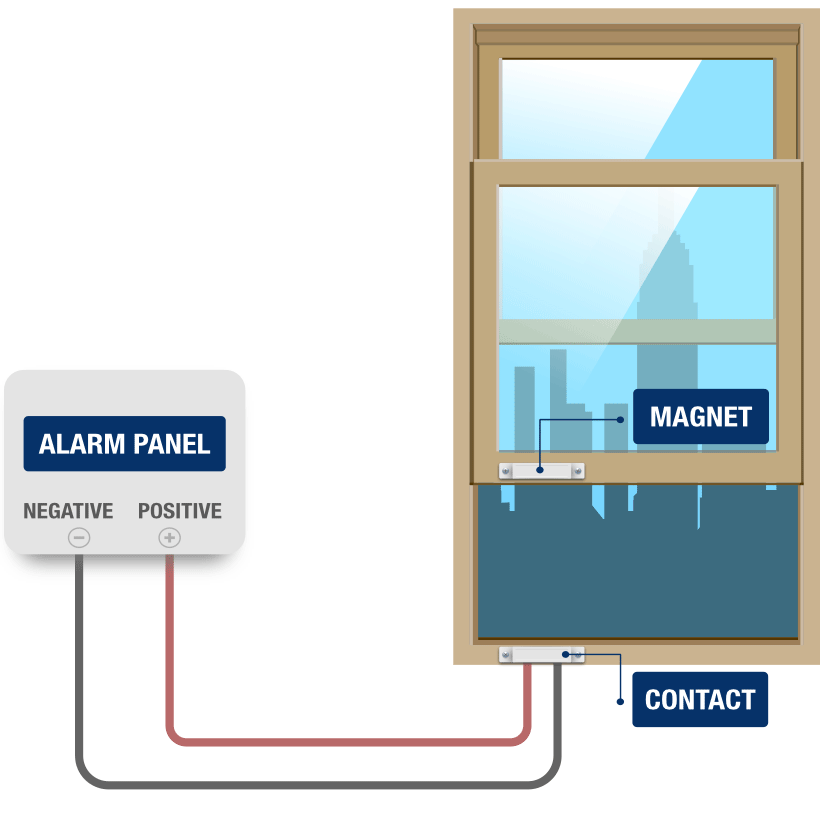
How an Alarm Circuit Works
An intrusion alarm
circuit consists of a pair of wires running from an intrusion alarm panel to a
sensor, such as a magnetic contact. Electrical charge flows from the positive
terminal, down one wire, and into the sensor. When something causes the sensor
to close, it completes the circuit, allowing the charge to flow down the other
wire and back to the negative terminal on the panel.
In the case
of the contact, the circuit is complete because the magnet causes the reeds to
touch, allowing current to flow from the reed on the positive side of the
circuit to the reed on the negative side.
Using a pair
of wires to connect both sides of the sensor to both terminals on the panel
creates a large circle, which is where the word circuit comes from.
The electrons flow freely all around this circuit, from the positive terminal
on the panel, through the sensor, and back to the negative terminal. Opening
the window will cause the reed to separate, which will break the circle and
stop the flow of electrons. In other words, opening a window will create
an open circuit. It is this open circuit that causes an alarm condition.
Loops vs
Splices
The two most
common ways to add multiple sensors to circuits is to
use loops or splices.
Loops are
preferred because it creates a short pathway, which means less resistance,
fewer points of failure and faster to install. However, loops can only
typically be used in new construction where the technician has the ability to
run wires and loops through the window frames before the drywall is installed.
Prewiring requires coordination with the general contractor or the carpenter.
The alarm company needs to be able to schedule a technician to complete the
wiring before the drywall crew is scheduled to begin installing drywall, and
the carpenter should be told where to drill holes on the moulding or window
frame.
Splices
should be minimized because they add resistance and are more time consuming to
install. However, adding alarms to exiting homes or businesses typically
require this since it is not feasible to open the drywalls to run a looped
circuit.
Two types of splicing
exists: field splice and ITB (in-the-box) splice. The benefits of field splices
are lower total circuit resistance and using less wire, but it requires a more
skilled technician to hide the splice. By contrast, ITB splices are easier to
troubleshoot, have fewer potential points of failure and they can be done by a
less experienced installer, but they have higher total circuit resistance and
require an installer to home run a wire to each individual window.
Loops Explained
The image
below shows an example of a loop that allows two windows to share a circuit.
Opening either the top sash or the bottom sash of either the right window or
left window will cause the same zone to open. To accomplish this, a technician
runs a single wire from one contact to another, allowing the current to travel
around the windows in a circle. The technician leaves a loop at every window,
which will bring the circuit in one side of the contact and out the other.
One wire of
the pair runs to the window on the right, and the other runs to the window on
the left. The technician has run loops of wires from one side of the contact to
the other. One side of the contact on the top right window has a loop running
to one side of the contact on the left (shown in black below). The loop between
the top left contact and the bottom left contact (shown in RED) completes the
circle, as long as all the windows are closed.
Field Splices
A field
splice is one that is made at the device end of the wire, usually at the device
itself. A skilled technician can make a field splice if the conditions are
right. Splices must be accessible for future troubleshooting, so a field splice
can only be made if there is someplace to hide them away from casual view. For
example, when wiring windows, a technician can staple the wire to the underside
of the frame or moulding, out of sight but easily found by an experienced /
certified intrusion alarm troubleshooter. Intrusion alarm installers commonly
wire all sirens and strobes in a location to a single circuit, and make field
splices inside the siren box.

In this
example, a pair of wires (green) is running to the alarm panel. Red wires are
running to magnetic contacts on the bottom sash and the top sash of the right
window, and blue wires are running to the top sash and the bottom sash of the
left window. One red wire is spliced to one blue wire, leaving one red wire and
one blue wire to be spliced to the green wires.
ITB Splices
ITB splices,
or in-the-box splices, are those made inside the alarm can.
Separate wires are run to each individual contact, and they are then joined up
at the panel using a splice.
ITB splices
are much easier for inexperienced technicians, and much faster to wire up.
Making ten splices, one after another, to add ten devices to five zones, is
faster than making a splice at every entranceway and then figuring out how to
tuck them away. They are also much easier to troubleshoot if properly labeled
in the can, because a troubleshooter can quickly isolate the circuit branch
causing the issue, and does not have to first find and identify the splice.
However, running individual wires is more more labor intensive, and uses more
wire.
Circuit Electrical Specifications
All devices
in an alarm, including unpowered devices such as contacts, require a specific
amount of charge flowing through the wires at a specific speed and pressure or
it will not work.
Every circuit has a voltage, current, and resistance value:
- Voltage is measured in volts (V).
- Current is measured in amps (A).
- Resistance is measured in ohms (Ω).
Voltage is a measurement of how much
electricity is available for use. Every device lists the amount of voltage it
requires to operate.
- If given too few volts, the device will either
not power up or will work erratically.
- If given too many volts, it will either shut
down or overheat.
Current is the pressure at which the
charge flows. All devices consume, or draw, electricity at a
predetermined rate.
- Not enough amps may cause the device to work
harder to draw voltage, which could cause it to either shut down,
overheat, or work erratically.
- Too many amps is not harmful as the device
cannot draw more current than it can use.
Resistance is anything that slows the current. Factors that increase
resistance are
- Number of connected devices
- Wire length
- Splices
- Time
- Copper oxidization
Too much
resistance on a circuit will lower the current, making it more difficult for
the alarm to monitor the zone properly. Since resistance increases in all
circuits as time goes on, improperly designed circuits have a high probability
of causing false alarms years after being installed. Therefore, every effort
should be made to keep the resistance as low as possible.
Parallel Versus Series
The two
methods of joining multiple sections to a single circuit are parallel and
series. Devices can either be wired in parallel or in
series with each other. Circuits using parallel splices are called
parallel circuits, and circuits using series splices are called series
circuits.
In
a series splice, one of the pair of wires is spliced to one the next pair
of. This way, no matter how many pairs of wires are added, the end result is
two wires that are simple to connect to two screw terminals. In between, lots
of wires are spliced to each other. This makes troubleshooting simpler, because
a technician can simply test a single branch of the circuit at a time. Series
is typically best for connecting a small number of devices to a circuit. It is
faster and easier to wire up. The downside is that series introduces a lot more
resistance if too many devices are connected.

In
a series circuit, the wires from each branch of the circuit will be
spliced together until two wires not spliced to anything are left. These single
conductors will be connected to the screw terminals, while the splices 'hang'
in the air, not connected to anything but each other. No matter how many
devices and wires are connected to the circuit, there will always be only one
wire to connect to the positive and one to connect to the negative.
Parallel
splices are typically best for connecting a large number of devices to a
single circuit, or for circuits that draw lots of power. It greatly reduces the
amount of resistance, allowing those large numbers of devices to be connected.
However, it is harder / more complicated to implement, will not work if done
incorrectly, and is more difficult to troubleshoot later on.
In a parallel
circuit, all the matching sides of the wire pairs are simply spliced together,
with the end result being two thick wire twists. This can be a challenge to
connect to screw terminals. In order to troubleshoot the wire going to a branch
of the circuit, a technician must first undo the entire splice.
Experienced
alarm technicians develop a 'feel' for when to splice devices in parallel and
when to splice in series. However, the key determinate is this: when a series
splice will result in too much resistance, a parallel splice must be used.
Before splicing anything, technicians can test a circuit in order to determine
the amount of resistance present.
Measuring Resistance
Resistance is
measured using a digital multimeter, or DMM. To measure resistance, turn the
function dial of meter to the Ω (ohms) symbol, and touch the leads to the bare
wires of the circuit. Technicians measure resistance in order to
- Test that all devices on a circuit are
functioning normally
- Decide whether to keep devices on a zone or to
split them up among multiple zones
- Decide whether a circuit should be wired in
series or in parallel
- Record a baseline resistance at the time of
installation
- Troubleshoot, as a zone with a resistance
reading well over baseline can indicate a broken wire or defective sensor
How Much Resistance Is Too Much?
There is no
clear answer to the precise amount of devices, and consequently the precise amount
of resistance, that should be allowable on a single detection circuit. As a
general rule of thumb, many installers try to keep the baseline resistance on a
single circuit to ~40Ω. Remember that the resistance will inevitably creep up
over time, depending on the number and nature of sensors connected to the
circuit, the number and nature of splices on the wire, the exact composition of
the wire, and even the environment, which could cause the wire to oxidize
faster or slower. The following animation shows the current slowing the more
devices are added to the circuit:

Different
alarm panel manufacturers have different standards for what constitutes an
alarm condition, but all those standards are based on the panel reading the
resistance on a zone circuit. If a circuit has a reading significantly higher
than 40Ω, consider either using a parallel splice or splitting the zone,
removing some devices from one zone and wiring them to a new zone.
Some
installers prefer ITB splices because it allows them to decide to split the
zone later on. If devices have been wired together using wire loops or field
splices, this is not possible.
How Many Devices Is Too Many?
In theory, an
installer can connect all the doors on a single zone, all the windows on
another zone, all the motion detectors on a third zone, and so forth. However,
this is quite an inefficient way of using an alarm. The more devices are on a
single zone, the harder it will be for the user to figure out which device is
causing the zone to be open.
If all the
windows in a room are on a single zone, the user will have to check all of them
before being able to arm the system. If a user wants to keep a single window
open while arming the rest of the system, they would have to bypass all the
windows in the room, which is a higher security risk than simply bypassing a
single window. If central station needs to dispatch police or fire to the
user's site, they will only be able to give a vague description of the location
of the problem, not a specific location.
Most panels
can only handle a limited number of zones out of the box. Using additional
zones requires purchasing and installing zone expanders, which add to the
overall cost of the installation. Using multiple zone expanders may require
adding a second can, which likewise adds to the cost. The question of when to
combine devices on a single zone and when to separate devices into separate
zones has no easy answer, but becomes clearer with experience.
Wiring Sirens
Wiring sirens is slightly different than wiring other alarm devices.
- Sirens are rated in watts, not volts like all
other alarm devices
- Watts are a measure of how much a power a
device outputs
- Volts a measure of how much power a
device uses
- Most sirens are rated to 30 watts
Most panels only have a single siren output. However, many applications
call for the volume to be lower on some sirens than on others. For example, a
siren mounted indoors would cause hearing damage if sounding at a full 110dB,
but 110dB is necessary for notification outdoors. In order to have different
volumes from a single output, installers can choose to wire sirens in either
parallel (for louder volume) or in series (for lower volume). They can even
choose to wire some sirens in parallel and other sirens in series. The sirens in
series have more resistance than the sirens in parallel, so that there is more
resistance, and therefore fewer watts, forcing the siren to sound at a lower
volume.
Intrusion
alarm siren wiring is a perfect illustration of Ohm's Law.
Ohm's Law
Understanding Ohm's Law makes alarm troubleshooting much easier. Ohm's
Law states that there is a direct relationship between volts, amps, and ohms,
specifically that volts equals amps times ohms. Amps is ohms divided by volts,
and ohms is volts divided by amps. Adding resistance (ohms) makes the current
(amps) go down, and adding current (amps) makes the resistance (ohms) go down.
The simplest way of lowering or raising the power available to the siren
is by raising or lowering the resistance. This raises or lowers the amount of
available power, which in turn affects the operation of the siren.
Understanding Ohm's Law can help a technician diagnose and repair power
supplies, sensors, circuits, and sensors. Changing a splice from series to
parallel, replacing a power supply for one that outputs the same voltage at a
higher amperage, or adding a resistor are all repair options that an installer
has once they understand how Ohm's Law works.
Source: IPVM.com & circuitstoday.com