Showing posts with label Camera PIR Sensor Integration. Show all posts

Saturday, January 1, 2022

Security Camera Input Setup

 Security Camera Input Setup

Artificial Intelligence (AI) security cameras are specialized network IP cameras that perform advanced analytical functions such as vehicle detection, person detection, face detection, traffic counting, people counting, and license plate recognition (LPR). These artificial intelligence functions are achieved using highly advanced video analytics software that is built-in to the camera and recorder they are connected to. AI cameras can be used as a stand-alone device by recording to an SD card, or they can be connected to a network video recorder (NVR) to create a multi-camera AI system that records to a central hard drive. Please note that only certain models are capable of license plate recognition / automated number plate recognition (ANPR).

A special characteristic some network video devices possess is an integrated input & output ports. This incorporation allows for the communication and interaction of external devices, such as but not limited to:
1.   Doorbells
2.   Switches
3.   Alarm System Relay
4.   Pressure strips
5.   Detectors (frequency, smoke, movement, sound, temperature, and humidity sensors)

All these functions can be achieved via:
1.   NVR/DVR (remote or local)
2.   Application through a smart device (Tablet or Phone)
3.  
Computer (local or remote / software or browser)


Camera / DVR / NVR Alarm Input

Motion sensors / motion detectors can be integrated with video surveillance systems to provide additional security for buildings and also outdoor areas. For example, a PIR sensor (passive infrared) can be connected to the alarm input of a security camera DVR or IP camera NVR to trigger video recording and send an alert to the property owner that motion has been detected in a certain area.

When motion is detected by the motion sensor, it triggers the following alarm actions.
1.   Trigger video recording on the camera associated with the alarm.
2.   Enable the alarm output on channel one, where I have an alarm light attached (turn the strobe light on).
3.   Pop-up live video of the camera associated with the alarm on the DVR’s display monitor.
Here are some additional actions that can be triggered from an alarm input.
1.   Capture a still image snapshot.
2.   Send a push notification to the mobile app for iPhone & Android.
3.   Enable the alarm buzzer on the DVR / NVR.
4.   Send an email notification.

The inputs and outputs can be used to eliminate unnecessary recording of video or coincide with your alarm system to systematically create a reliable and accountable security source. When input and output mechanisms are triggered, you can (manually or automatically) request through the network video device that certain actions be performed over the network as well as trigger devices attached to the output ports. Example:

This example picture above shows a person interrupting a sensors function. This creates a signal that travels to the camera and the camera computes the message. The camera then functions as programmed and starts recording (snapshots or footage) to the delegated device while simultaneously triggers a relay to close. When the relay closes, it completes the circuit for the siren or strobe to activate. Another configuration (as long as the cameras capable), have the camera record to the desired method based on motion and simultaneously trigger the relay to set off the siren. In this example, a motion sensor is taken out of the equation.

Again, the above picture shows only one of many configurations. You can configure in whatever method you desire. Including or excluding recording methods based off of:
·        Motion (movement takes place)
·        Masking (the camera has been covered or obstructed significantly)
·        Video Loss (picture is no longer materializing, this feature is more prone to function correctly via a recorder or program)

Other devices that can be attached and configured to your I/O ports are as follows:

Device Type

Description

Occurrence of activation

Entry Contacts

Simple magnetic sensors detecting opening of doors, windows, gates and shutters.

When the circuit is broken (door is opened) the camera can record and/or send a snapshot and notifications

Motion Sensors

A sensor that detects motion either based on heat, light, or frequency

When motion is detected, the sensor breaks the circuit and  the camera can record and/or send a snapshot and notifications

Glass Break or Glass Shock Sensor

A sensor capable of distinguishing the sound/vibration of breaking glass and/or splintering wood.

When glass is  disturbed or shattered, the glass sensor breaks the circuit and the camera can record and/or send a snapshot and notifications

Pressure strip or switch

A pressure or switch sensor that are needed to interact with before gaining entry or exiting a premise or structure

When the sensor is triggered it breaks the circuit and the camera can record and/or send a snapshot and notifications


How-to Install Motion Detectors with a Security Camera System

Installing a motion detector and integrating it with a security camera system is fairly simple. CCTV Camera Pros supports professional and DIY installers. Most PIR motion sensors are 12V DC powered which gives installers the choice of using a individual 12V DC power supply or one of the ports on a multi-channel power supply box (the same ones used with security cameras).

In this first diagram, a single 12V DC power transformer is used. This is how it works.

1.   On 
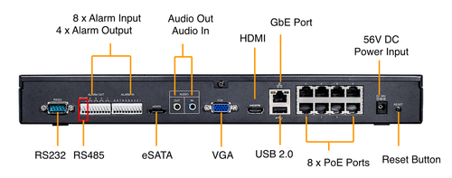
the right side of the diagram, the alarm input / output panel of the DVR is shown. This is what the alarm panel on the back.

2.   18/2 gauge power cable connects the output of the motion detector to one of the alarm input ports on the DVR.

3.   18/2 gauge power cable is also used to connect the motion detector to an individual DC power supply.

4.   A PT-4 power lead connects the raw cables to the 3.1mm plug on the power supply.

Installation with Power Supply Box

A multi-channel power supply box can be used instead of an individual power supply.

This installation is the same as the one above using the single power supply. The only difference is the use of a multi-channel power supply box to power the motion detector. CCTV Camera Pros supplies many of these power boxes for security camera installations. These power boxes can be shared with cameras and 12V DC powered alarm sensors. Because power supply boxes use screw based wire terminals, there is no need to use a PT-4 power lead (as with the individual power supply installation). Same connection for Camera & NVR.

Most of Camera PIR motion sensor is located on the front of the camera, just below the camera lens. This motion sensor is designed to detect movement of human sized objects when they come into view of the camera’s lens. The camera has a 2.8-12mm varifocal lens which when adjusted to the widest angle (the 2.8mm setting) the camera provides a 109 degree horizontal field of view. The PIR sensor detects motion across a 100 degree field of view. Please note that if you adjust the lens to a more narrow field of view, this does not effect the area where the PIR sensor will detect motion.
In my experience, using a PIR sensor based motion detection is much more reliable than software based video motion detection (especially for outdoor video surveillance). Typically there are a lot of small moving objects outdoors which makes it difficult to get the sensitivity just right. When security cameras turn to night mode, there is typically some video noise because of the lack of light. This noise can cause false alarms when using video motion detection. A PIR sensor uses infrared light to measure the radiation reflected by objects in its view. When a certain amount of this radiation changes, the PIR sensor triggers an alarm, so they are not susceptible to some of the challenges of outdoor video motion detection.

FAQ

Here are some frequently asked questions about integrating PIR motion detectors with security camera systems.

·        How are motion detectors used with security camera systems?
The most common way to integrate a motion detector with a security camera system is to hard wire the motion detector to the same surveillance DVR that your security cameras are connected to. You must make sure that your DVR that has alarm inputs.

·        Can I just use motion detected from my security camera instead of an external motion sensor?
Yes, most DVRs support video motion detection triggered by cameras. Please note that this is different from PIR (passive infrared) motion detection and can be less reliable. Video motion detection tends to produce more false positives than PIR motion detection, especially in outdoor and infrared camera applications. This is because the video tends to be more noisy and outdoor environments tend to always have some motion from wind and other natural elements.

·        What type of cable is used to wire motion detectors to DVRs?
The following types of cable can be used to wire motion detectors: CAT-5 cable (one pair), 18/2 conductor power cable.

·        Do motion detectors require power?
Yes. Most PIR motion detectors use 12V DC power. All of ours include the proper power supply with them.

·        Can I use multiple motion detectors with my surveillance system?
Yes, as long as your DVR has multiple alarm input ports, you can use multiple motion detectors. Different model DVRs support different numbers of alarm inputs so consult the specification or contact us if you need help.

Not every camera or NVR/DVR possesses this unique features or can be operated through the above mentioned methods. Be sure you research everything you will need to make this type of setup successfully work for you. This includes the correct relays, power supplies, capable camera and recording devices. Most our IP mega pixel cameras and recorders have the capability of all previous mention features above.

If you are not understand, you can touch with us for further support. We deal Infinova, Hanwha, Milestone, Mirasys & Luxriot brand.


Saturday, February 18, 2017

HOW TO USE IP CAMERA ALARM I/O

How to use ip camera alarm i/o
As we know, professional IP cameras have alarm input and output interface for security integration solution. Users can use this interface to connect other security devices such as PIR motion sensor, door sensor, perimeter beam sensor...etc. This article is intended to give a guideline for connecting alarm input/output interface of Vivotek, Axis, Sony, HikVision, Dahua, Messoa,...and more IP cameras. 

KNOWING ALARM I/O (INPUT / OUTPUT)
Alarm Input / Alarm Output is a pair of pins in camera's terminal block or connector through which it's possible to connect electronic device with the camera. Alarm Input receives signal from external device, will be triggered from external device if something changes, and Alarm output notifies the external device by the camera upon a event (motion detection, vandalism, video loss).

The terms "Alarm In / Alarm Out" are mainly used as the application for alarm system, but they are also called digital input (DI) / Digital Output (DO) as the common terms.

External device connected to Alarm In can be a switch (or say relay), button or any device which can issue a trigger signal. External device connected to Alarm Out can be a light, alarm horn/siren or any kind of device which receives data.

SHOULD I USE CAMERA'S ALARM I/O?
The main benefit of using camera's Alarm Input / Alarm Output is to respond to the event instantly and automatically by a pre-defined event scheme, and give alert message immediately so that the monitoring control center can handle any situation in a short time to reduce hazard.

CAMERA'S ALARM INPUT/OUTPUT
(1) Terminal Block Type: use 2-pin connector to connect wire
Dahua IP Camera - Terminal Block
Hikvision IP Camera - Terminal Block
Messoa IP Camera - Terminal Block
(2) Connector Type: connect wire directly
*Alarm Out (Orange): Connect to a device that responds to alarm signals, such as buzzers or lights.
*GND: Ground (electricity) in electrical circuits
*Alarm In 1 (Red) & 2 (Brown): Connect to devices that issue alarm signals. Up to two (2) input devices can be selected.
Messoa Camera Alarm Input / Output
CONNECTION EXAMPLE 
1.      Connect Alarm In via a switch to GND: Simply  connecting  Alarm In_1  via a switch to  GND with a single wire,  as shown above, the  Alarm In_1 will be instantly triggered by a press on switch. You do not have to have an external battery to make the “switch” work.
The example circuit of Alarm In: Alarm In 1 –> Switch (OPEN by default) –> Ground
2.      Connect Alarm Out: The Alarm out is an open-drain structure, so you have to  supply external power source  to make the function work.
The example circuit of Alarm Out: DO 1 –> LED (load) –> +[battery]- –> Ground
3.      Enable External Alarm: Access the IP camera via Internet Explorer, go to camera's configuration page to enable External Alarms. Enable the Alarm In/Out that is connected with external alarm devices and set the voltage level as low or high to define the active state.
4.      Validate the setting by pressing the switch and check if it triggers the LED instantly.
The alarm output ports on the back of IP camera can be connected with a siren or strobe light. Below it's a connection example. The goal is to turn the siren/strobe light on when an alarm is triggered. The working theory is pretty simple, you can imagine the alarm output is a turn on/off switch. In below connection diagram, you need to use extra power supply (for example a AC/DC adapter) to provide the power for strobe siren.

For DVR Click at DVR Alarm
The IP camera's alarm inputs are grounding alarm inputs (Normal open or Normal close type). Hardwired sensor or device can parallel connect ground (-) end and COM end of the alarm detector, while parallel connect the NO (+) end and NC end of the alarm detector. (Please note that you need to provide external power to the detectors)
In the above connection diagram, the DG85 (motion sensor)'s NC connects the positive (+) alarm input of IP camera, and the DG85 (motion sensor)'s COM (or GND) connects the negative (-) alarm input of IP camera. (This is NC connection, you need to choose the IP camera's alarm input property to NC.)
You can make connection between IP camera and hard-wired/wireless alarm panel. Connect the alarm output of IP cameras to hardwired zones of alarm panel. Please note that you need to use the EOL resistor in this connection. The EOL resistor can protect the circuit of wiring to prevent short-circuit or cut. The EOL resistor should be installed in the end of IP camera.
With correct connection, the IP camera can send signal to alarm system for associated alarm action.
Two different connection are available:
1.      When alarm output (IP camera) is NC:You need to do the normal close connection. The EOL resistor should connect into circuit in series connection.
2.      When alarm output (IP camera) is NO: You need to do the normal open connection. The EOL resistor should connect into circuit in parallel connection.


Normal Open (NC) and Normal Close (NO) explanation
Normal Open: When the device is in the non-triggered state, it's normally closed means that the circuit can allow current to flow from NC to COM, or it turns ON. When the alarm is triggered, the relay is enabled and it will switch from the normally closed (NC) to normally opened (NO) or from Turn ON to Turn OFF.

Normal Close: When the device is in the non-triggered state, it's normally opened means that the circuit is open, it doesn't allow current to flow from NO to COM, or it turns OFF. When the alarm is triggered, the relay is enabled and it will switch from normally opened (NO) to normally closed (NC) or from Turn OFF to Turn ON.