It is very important to setup a static ip
address, if you are going to use port forwarding. When you have port forwarding
setup, your router forwards ports to an ip address that you specify. This will
probably work when you initially set it up, but after
restarting your computer it may get a different ip address. When this happens
the ports will no longer be forwarded to your computer's ip address. So the
port forwarding configuration will not work.
What is an ip address?
IP addresses are four sets of numbers separated by periods that allow computers to identify each other. Every computer has at least one ip address, and two computers should never have the same ip address. If they do, neither of them will be able to connect to the internet. There is a lot of information at the following link. You don't need all of it. But if you want to know more about how networks work, you'll find it there.
IP addresses are four sets of numbers separated by periods that allow computers to identify each other. Every computer has at least one ip address, and two computers should never have the same ip address. If they do, neither of them will be able to connect to the internet. There is a lot of information at the following link. You don't need all of it. But if you want to know more about how networks work, you'll find it there.
Dynamic vs Static IPs
Most routers assign dynamic IP addresses by default. They do this because dynamic ip address networks require no configuration. The end user can simply plug their computer in, and their network will work. When ip addresses are assigned dynamically, the router is the one that assigns them. Every time a computer reboots it asks the router for an ip address. The router then hands it an ip address that has not already been handed out to another computer. This is important to note. When you set your computer to a static ip address, the router does not know that a computer is using that ip address. So the very same ip address may be handed to another computer later, and that will prevent both computers from connecting to the internet. So when you asign a static IP addresses, it's important to assign an IP address that will not be handed out to other computers by the dynamic IP address server. The dynamic IP address server is generally refered to as the dhcp server.
Most routers assign dynamic IP addresses by default. They do this because dynamic ip address networks require no configuration. The end user can simply plug their computer in, and their network will work. When ip addresses are assigned dynamically, the router is the one that assigns them. Every time a computer reboots it asks the router for an ip address. The router then hands it an ip address that has not already been handed out to another computer. This is important to note. When you set your computer to a static ip address, the router does not know that a computer is using that ip address. So the very same ip address may be handed to another computer later, and that will prevent both computers from connecting to the internet. So when you asign a static IP addresses, it's important to assign an IP address that will not be handed out to other computers by the dynamic IP address server. The dynamic IP address server is generally refered to as the dhcp server.
Setting up a static
ip for Windows 7.
If you have a printer, before you begin print out this page!
Step 1:
Open up the start menu, and look for the Search programs and files box. You should now see the following window.
If you have a printer, before you begin print out this page!
Step 1:
Open up the start menu, and look for the Search programs and files box. You should now see the following window.

Step 2:
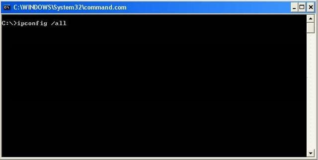
Type cmd in the Search programs and files box, and press Enter on your keyboard. The will bring up a black command prompt window.
Type cmd in the Search programs and files box, and press Enter on your keyboard. The will bring up a black command prompt window.
Step 3:
The command prompt may look different on your screen, but it doesn't really matter. Type ipconfig /all in that window, and then press the enter key. This will display a lot of information. If it scrolls off the top you may need to enlarge the window.
The command prompt may look different on your screen, but it doesn't really matter. Type ipconfig /all in that window, and then press the enter key. This will display a lot of information. If it scrolls off the top you may need to enlarge the window.

Step
4:
I want you to write down some of the information in this window. Take down the IP address, Subnet Mask, Default Gateway, and Name Servers. Make sure to note which is which. We are going to use this information a little bit later. We are only concerned with IPv4 entries, you can ignore the IPv6 stuff.
The name server entries are a bit complicated. Name Server is just another name for DNS(domain name server) server. Some router's act as a proxy between the actual name servers and your computer. You will know when this is the case, because the Default Gateway will list the same ip address as the Name Servers entry. We need to have the correct Name Server IP addresses. If we do not, you will not be able to browse the web. There are a couple ways to get these. The first way is to log into your router's web interface, and look at your router's status page. On that page you should see an entry for DNS Servers, or Name Servers. Write down the ip adresses of your Name Servers. Another way to get the correct Name Servers to use, is to give your ISP a call. They should know the ip addresses of your Name Servers right off. If they ask you why you need them, you can tell them you are trying to setup a static IP address on your computer. If they try to sell you a static external ip address, don't buy it. That's an entirely different thing that what you are trying to setup.
Type exit in this window, then press the enter key to close it.
Step 5:
Once again open the start menu. This time click Control Panel.
Once again open the start menu. This time click Control Panel.

Step 6:
Click on View Network Status and Tasks.
Click on View Network Status and Tasks.

Step 7:
Single click Change adapter settings on the left side of your screen.
Single click Change adapter settings on the left side of your screen.

Step 8:
You might have more than one Internet connection listed here. You will need to determine which adapter is your connection to the Internet if this is the case. Right click on your network adapter and choose properties to open up the properties window of this internet connection.
You might have more than one Internet connection listed here. You will need to determine which adapter is your connection to the Internet if this is the case. Right click on your network adapter and choose properties to open up the properties window of this internet connection.
Step 9:
Click Internet Protocol Version 4(TCP/IPv4) and then the Properties button.
Click Internet Protocol Version 4(TCP/IPv4) and then the Properties button.

Step 10:
Before you make any changes, write down the settings that you see on this page. If something goes wrong you can always change the settings back to what they were! You should see a dot in the Obtain an IP address automatically box. If you do not, your connection is already setup for a static ip. Just close all these windows and you are done.
Pick an ip address and enter it into the IP Address box. The ip address you choose should be very similar to the router's ip addres. Only the last number of the ip address should be different. If the router's ip address is 192.168.1.1, I might choose 192.168.1.10. The ip address you choose should end with a number between 1 and 254, and should not be the same as the router's ip address. Every device that connects to your network needs to have it's own ip address.
Put the subnet mask we previously found in the subnet mask section. The default gateway should go into the Default gateway box. Enter the dns servers we prevoiusly found into the two DNS Server boxes. Click okay all the way out of this menu.
If you find that you can not pull up webpages, the problem is most likely the dns numbers you entered. Give your ISP a call, and they will be able to tell you which dns servers to use. This is a question they answer all of the time. They will be able to tell you what you should use right away.
That's it you should be done! If you can't connect to the internet go back and change your configuration back to what it originally was.