Saturday, October 17, 2015

D-Link Port Forwarding of DVR

D-Link Port Forwarding - DIR 615 - DIR-825 - DIR-655 - DIR-628 - DIR-628
D-Link port forwarding, also known as virtual server, allows you to configure inbound Internet connections to your router to be routed to specific devices on the network.  In order for surveillance system cameras to be accessible over the Internet, your router is configured to forward requests to your surveillance DVR or directly to IP cameras.  The IP address that your router assigns to your DVR or to IP security cameras is a LAN (internal IP address) that cannot be accessed from outside of your local network.

These instructions are for more recent D-Link routers such as the following: DIR-615, DIR-825, DIR-655, DIR-628.
1.     Open your D-Link router's control panel by going to the IP address http://192.168.0.1/ in a web browser. You will be prompt for a password.  If you did not setup a password on your router, the dlink default password is usually blank.  Enter admin for the username and leave the password blank or enter your password.
2.     After you are logged into your router

1. Click on the "Advanced" tab (#1 below). The virtual server screen will open.
2.     Click the check box next to the first open virtual server entry and fill in the Name for this service.  This can be anything that you choose.  Also fill in the IP address of the device that you are setting up port forwarding for.
3.     Enter the port # for both the Private Port and Public Port.  Ports 80, 4550, and 5550 are the ports that need to be forwarded for Some DVR webcamserver to work.  You need to make an entry for each port.  Most of our stand alone DVRs only use one port which should be supplied on the instructions for the particular DVR you are installing.
4.     Select "TCP" for Protocol.
5.     Select "Always" for Schedule, and "Allow All" for Inbound Filter.
6.     Click Save Settings.
2.     On success, the screen will display a settings saved screen

The port forwarding entry is now added.  If you need to add additional port forwarding rules, repeat the above steps.

Saturday, October 10, 2015

32-bit and 64-bit CPU

32-bit and 64-bit CPU


If you are CCTV technicians you need to know the two main categories of processors are 32-bit and 64-bit. The type of processor a computer has not only affects it's overall performance, but it can also dictate what type of software it uses.
32-bit processor
The 32-bit processor was the primary processor used in all computers until the early 1990s. Intel Pentium processors and early AMD processors were 32-bit processors. The Operating System and software on a computer with a 32-bit processor is also 32-bit based, in that they work with data units that are 32 bits wide. Windows 95, 98, and XP are all 32-bit operating systems that were common on computers with 32-bit processors.
64-bit processor
The 64-bit computer has been around 1961 when IBM created the IBM 7030 Stretch supercomputer. However, it was not put into use in home computers until the early 2000s. Microsoft released a 64-bit version of Windows XP to be used on computers with a 64-bit processor. Windows Vista, Windows 7, and Windows 8 also come in 64-bit versions. Other software has been developed that is designed to run on a 64-bit computer, which are 64-bit based as well, in that they work with data units that are 64 bits wide.

Differences
The main difference between 32-bit processors and 64-bit processors is the speed they operate. 64-bit processors can come in dual core, quad core, and six core versions for home computing (with eight core versions coming soon). Multiple cores allow for increase processing power and faster computer operation. Software programs that require many calculations to function operate faster on the multi-core 64-bit processors, for the most part. It is important to note that 64-bit computers can still use 32-bit based software programs, even when the Windows operating system is a 64-bit version.
Another big difference between 32-bit processors and 64-bit processors is the maximum amount of memory (RAM) that is supported. 32-bit computers support a maximum of 3-4GB of memory, whereas a 64-bit computer can support memory amounts over 4 GB. This is important for software programs that are used for graphical design, engineering design or video editing, where many calculations are performed to render images, drawings, and video footage.

One thing to note is that 3D graphic programs and games do not benefit much, if at all, from switching to a 64-bit computer, unless the program is a 64-bit program. A 32-bit processor is adequate for any program written for a 32-bit processor. In the case of computer games, you'll get a lot more performance by upgrading the video card instead of getting a 64-bit processor.

In the end, 64-bit processors are becoming more and more commonplace in home computers. Most manufacturers build computers with 64-bit processors due to cheaper prices and because more users are now using 64-bit operating systems and programs. Computer parts retailers are offering fewer and fewer 32-bit processors and soon may not offer any at all.

Saturday, October 3, 2015

Bit Rate

Bit Rate For DVR, NVR & IP Camera

What are Bit Rates?
Let’s start with “what is a bit, and “why do I need to know?” A bit is short for “binary digit”, the smallest unit of information in computing. It takes 8 bits to make a byte of information. “Bit rate” refers to the number of bits of data transferred in a file over a set length of time usually measured in number of “bits per second” or “bps”.
Constant bit rate (CBR) and variable bit rate (VBR) are the main types of bit rate encoding. Scene complexity can vary significantly over several hours of recorded video, and the bit rate you select for recording will have an effect on image quality, bandwidth consumption, and hard drive storage. A complex scene with moving action, such as traffic on a city street, or a scene with a lot of contrasting colors, will affect image quality and bandwidth consumption more than a less complex scene, such as an interior room with very little action or movement.
Most NVRs and IP cameras let you choose either constant or variable bit rates for recording video, and this is why you “need to know” the difference.

Constant Bit Rate (CBR)
With constant bit rate encoding, a fixed bit rate and bandwidth is used throughout the entire encoded video file. With a constant bit rate, image quality may fluctuate over the course of the video stream because some scenes are more difficult to render than others. In order for the bit rate to remain constant, the video may be encoded with fewer bits in some places or more bits in other places resulting in inconsistent image quality. Since bandwidth consumption with constant bit rates does not vary, the file size is limited and more predictable than with variable bit rates.
You will most commonly use CBR to restrict the data flow to keep network utilization as low as possible. If you have 10 cameras set to 8000K (8 megabits) on a 10/100 LAN, you are using 80% of your available bandwidth. With CBR, you can set that bit rate down to 5000K and your utilization will be around 50%.
Pre-planning your security video storage requirements is easier with constant bit rate because the amount of data being recorded never changes.

Variable Bit Rate (VBR)
With variable bit rate encoding, a changeable bit rate and bandwidth is used throughout the encoded video file. The variability of bit rates allows for video to be recorded at a lower bit rate when the  scene on screen is less complex and at a higher bit rate when the scene is more complex. Complex scenes (such as moving traffic) require more data and greater bandwidth to maintain image quality  than less complex scenes such as a wall or hallway with very little movement or action. With variable bit rates, the quality of video is higher and more consistent throughout the video stream compared to constant bit rates, yet the file size is less predictable.

Image quality is better with variable bit rates than with constant bit rates, yet pre-planning your security video storage requirements is more difficult because the bit rate changes and more complex scenes will require greater bandwidth and storage.

Here’s a Quick Look at How Constant and Variable Bit Rates Compare:
Constant Bit Rates
Variable Bit Rates
Variable video image quality
Consistent video image quality
File size is predictable because bit rate and bandwidth consumption is fixed
File size is unpredictable because bit rate and bandwidth consumption varies
Greater compatibility with most systems (compared to variable bit rate)
Less predictable compatibility (compared to constant bit rate)
When to use: When you need to limit file size and the quality of video is less important.
When to use: When consistent image quality is critical and predicting or limiting file size is less important.
The best of both worlds is when the device allows you to set VBR with a ‘Cap’ or maximum allowed bit rate.

Here is a handy ‘Quick Reference’ for setting a constant Bit Rate in bits per second.
Low Activity
Compression
Frame Rate
VGA/D1
720P/1.3MP
1080P/3MP
H.264
25~30
768K
2000K
3000K
15~20
512K
1500K
2000K
8~10
386K
1000K
1500K
2~5
256K
768K
1000K
MPEG4
25~30
1000K
3000K
5000K
15~20
768K
2000K
4000K
8~10
512K
1500K
3000K
2~5
386K
1000K
2000K

Normal Activity
Compression
Frame Rate
VGA/D1
720P/1.3MP
1080P/3MP
H.264
25~30
1000K
3000K
5000K
15~20
768K
2000K
4000K
8~10
512K
1500K
3000K
2~5
386K
1000K
2000K
MPEG4
25~30
1500K
4000K
6000K
15~20
1000K
3000K
5000K
8~10
768K
2000K
4000K
2~5
512K
1500K
3000K

High Activity or PTZ on Tour
Compression
Frame Rate
VGA/D1
720P/1.3MP
1080P/3MP
H.264
25~30
2000K
4000K
6000K
15~20
1500K
3000K
5000K
8~10
1000K
2000K
4000K
2~5
768K
1500K
3000K
MPEG4
25~30
3000K
6000K
8000K
15~20
2000K
4000K
6000K
8~10
1500K
3000K
4000K
2~5
1000K
2000K
3000K
In the bit rate charts above, you will see 1000K / 2000K etc. These figures can be loosely translated into ‘megabits’ per second.
1000K = 1Mb | 2000K = 2Mb and so on.

(In the computing world you would actually use 1024K = 1Mb and 2048K = 2Mb, but since most CCTV devices won’t allow those exact numbers, we just round them down to the closest thousand.) These figures are important to familiarize yourself with to manage your network load.

For example – 1 camera running a high bitrate of 8000Kbps (8Mbps) is no problem on a 10/100 network. 10 cameras at that bit rate = 80Mbps. 80Mbps is 80% network utilization on a 10/100 LAN. This is enough to see visible slowdown on the network and may begin to cause problems.

Switch to a Gigabit LAN and that becomes 8% utilization. Always check the capabilities of the network you are installing on – this can save you from a lot of headaches. When using IP cameras, always use Gigabit routers and switches when possible.  Also, make sure your NVR is connected to a gigabit switch. Plugging your NVR in to a 10/100 switch will limit your NVR to a 100Mb connection.

And finally – here is a “loose rule of thumb” for setting a bitrate:
[image width] x [image height] x [framerate] x [motion rank] x 0.07 = [desired bit rate]

Where the image width and height is expressed in pixels, and the motion rank is a number between 1 and 4. 1 being low motion, 2 being medium motion, and 4 being high motion (motion being the amount of image data that is changing between frames.).

So for instance, if we take a 1280×720 video at 24 FPS, with medium motion (movie with slow camera movements, not many scene changes…), the expected ideal bit rate would be:
1280 x 720 x 24 x 2 x 0.07 = 3,096,576 bps => approximately 3000 kbps, or 3MB
Remember – bit rates are not “universal” – different cams will give different results due to variations in encoding methods, hardware, and environmental conditions. Watch for artifacts like “ghosting” or “smearing” of moving objects.

Ghosting = when someone moving across the image may appear transparent, or may have a “ghost” following them. The “ghost” is not always transparent and may look like two people overlapped.

Smearing = when a moving object causes objects around it to change in appearance or starts to become pixilated.

Pixilated = When objects become unclear – may appear as a “smear” or slightly out of focus. In worst cases you will begin to see blocks of similar colors instead of the object itself.

Tuesday, September 22, 2015

RS-232 cable Wiring & Testing

COM Port (OR) RS-232 cable Wiring & Testing


As A technical background eSecurity Professional, many time got call “my Access Controller communication has RS232 enable How we connect with Computer (COM Port), is there any layout” Sometime “Successfully testing via my Laptop but Customer computer not responding, any distance or new programming is there”. I remember in year 2006 me also facing this type of problem with an Access Controller; I would be like to share the myth.

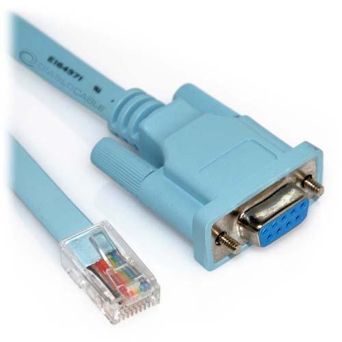
Com Port (Com1 / Com2 etc)= Serial Port = RS232 = Consol.

The wiring of RS232 has always been a problem. Originally the standard was defined for DTE (data terminal equipment) to DCE (data communication equipment connection), but soon people started to use the communication interface to connect two DTEs directly using null modem cables. No standard was defined for null modem connections with RS232 and not long after their introduction, several different wiring schemes became common. With Digital Equipment Corporation tried to define their own standard for serial interconnection of computer devices with modified modular jack connectors. This interfacing standard became available on most of their hardware, but it wasn't adopted by other computer manufacturers. Maybe because DEC used an non-standard version of the modular jack.


Very interesting is the RS232 to RJ45 wiring standard proposed by Dave Yost in 1987, based on earlier wiring schemes used at Berkeley University. He tried to define a standard comparable to DEC, where both DTEs and DCEs could be connected with one cable type. This standard was published in the Unix System Administration Handbook in 1994, and has since that moment been a wiring standard for many organizations. We will discuss this standard in detail here.
The RS-232 standard 9600bps port will drive 13 metres of shielded cable. RS232 standard is an asynchronous serial communication method. The word serial means, that the information is sent one bit at a time. Asynchronous tells us that the information is not sent in predefined time slots. RS232 sending of a data word can start on each moment. If starting at each moment is possible, this can pose some problems for the receiver to know which is the first bit to receive. To overcome this problem, each data word is started with an attention bit. This attention bit, also known as the start bit, is always identified by the space line level. Directly following the start bit, the data bits are sent. Data bits are sent with a predefined frequency, the baud rate. Both the transmitter and receiver must be programmed to use the same bit frequency. After the first bit is received, the receiver calculates at which moments the other data bits will be received. It will check the line voltage levels at those moments. With RS232, the line voltage level can have two states. The on state is also known as mark, the off state as space. No other line states are possible. When the line is idle, it is kept in the mark state. For error detecting purposes, it is possible to add an extra bit to the data word automatically. The transmitter calculates the value of the bit depending on the information sent. The receiver performs the same calculation and checks if the actual parity bit value corresponds to the calculated value. The stop bit identifying the end of a data frame can have different lengths. Actually, it is not a real bit but a minimum period of time the line must be idle (mark state) at the end of each word. On PC's this period can have three lengths: the time equal to 1, 1.5 or 2 bits. 1.5 bits is only used with data words of 5 bits length and 2 only for longer words. A stop bit length of 1 bit is possible for all data word sizes.
Goals of the Yost device wiring standard
The mess with RS232 wiring is widely known. It was the reason for starting this website. Dave Yost wanted to solve that mess once and for all, reaching as much as possible of the following goals:
  1. All cable connectors should have the same connector type (RJ45)
  2. All cable connectors should have the same connector gender (male)
  3. DTEs and DCEs should have the same connector wiring
  4. All cables should be identical (except for length)
  5. No need for null modems or other special cables for specific situations
These goals are very close to the goals DEC wanted to achieve. The Yost standard has however one basic advantage. Because RJ45 connectors are used, eight pins are available which makes it possible to transfer almost all RS232 signals. Therefore the Yost standard can be used with much more equipment.
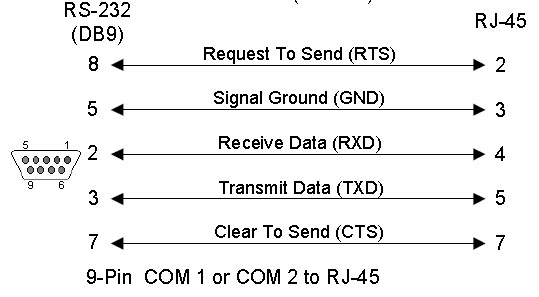
Yost DTE adapter wiring
Now we know how the cables are wired, it is time to define the adapter wiring for various equipment. Depending of the type of equipment, DB9 or DB25 connectors are used. Layouts for both connectors to a RJ45 socket for DTE equipment is shown here. The colors are defined by the Yost standard. The DTR to DSR connection is optional. Please use the manual of the device or software to decide if this loop is necessary. It doesn't harm most of the time if you connect both lines, even with systems that don't use the DSR input signal.
Test COM port by using HyperTerminal.
The HyperTerminal application has been distributed with the Windows operating system versions for a long time now, and for administrators and technical support Representatives, it can be a very useful tool. HyperTerminal allows a user to make a connection to a "host" system from a Windows computer using an available COM port. This will enable you to verify whether or not a port is active and open.  If you have never looked at HyperTerminal, take a couple of minutes to read through the following and see how it can make your life easier.
The HyperTerminal application is started by default from the Start | Programs | Accessories | Communications | HyperTerminal location. When you start HyperTerminal, you are asked to name the connection you are about to configure. This is useful as once you have configured your connection, you can then save all the settings to a configuration file of the same name. This configuration file can be used to implement equivalent settings for subsequent connections. After selecting a connection name, click OK.
On the Connect To dialog box, you are introduced to the different types of connection that HyperTerminal offers. By default, a dial-up connection using a modem is selected (assuming you have a modem present). If you have installed an external modem in addition to an internal modem that modem should also be present in the drop down menu as a choice.
 If you click the downwards arrow on the Connect Using field, you may see one or more COMx (where x is the number of the COM port. i.e COM5) options depending on the number of serial ports available on your computer. The COMx options are typically used for attaching to something like a UNIX computer via serial cable or to a router via its serial console cable. 

To test a specific COM port select that COM port you wish to test. Once the COM port is selected you will not be able to access the other options on this dialog box. They will appear grayed out.

Click OK and select these options:
9600 Bits Per Second, 8 Data Bits, No Parity, 1 Stop Bit, and Hardware Flow Control.
Before clicking OK on the COM3 Properties Dialog Box look at the lower left corner of the HyperTerminal Window. Notice it says "Disconnected" See graphic Below.
Now click the OK button on the COM3 Properties Dialog box. Watch the lower left corner of the HyperTerminal Windows. If the COM port is available and can be opened you will see the status change to Connected. See graphic below.
 If you select OK and get an error saying "Unable to open COMx (where x is the COM port number). Please check your port settings". The COM port you are testing is being used by some device or is not functioning correctly.
Start at the beginning of the COM port test and test another available COM port.
If you receive the error we discussed on every port you select then there are no available ports and you will need to either troubleshoot further or speak to your hardware manufacturer and ask your manufacturer to recommend a hardware solution appropriate for your situations.

Test COM port by using Loopback tester
This is a simple and useful tool for testing RS-232 ports in DTE equipment are working working or not. This plug is connected so that every sent character is echoed back.
 If you Short DB9 (Com Port / RS232) Pin 2 & 3, & Press any Word via Keypad, you can get Eco of that Key. IF you got replied then your Com port is Working Normal, IF not then need to either troubleshoot further or speak to your hardware manufacturer and ask your manufacturer to recommend a hardware solution appropriate for your situations.

Differences between RS-232 and full-duplex RS-485

From a software point of view, full-duplex RS-485 looks very similar to RS-232. With 2 pairs of wires -- a dedicated "transmit" pair and a dedicated "receive" pair (similar to some Ethernet hardware), software can't tell the difference between RS-485 and RS-232.
From a hardware point of view, full-duplex RS-485 has some major advantages over RS-232 -- it can communicate over much longer distances at higher speeds.
Alas, a long 3-conductor cable intended for RS-232 cannot be switched to full-duplex RS-485, which requires 5 conductors.
RS-232 is only defined for point-to-point connections, so you need a separate cable for each sensor connected to a host CPU. RS-485 allows a host CPU to talk to a bunch of sensors all connected to the same cable.

Differences between RS-232 and half-duplex RS-485

But a lot of RS-485 hardware uses only 1 pair of wires (half-duplex). In that case, the major differences are
  • Each RS-485 node, including the host CPU, must "turn off the transmitter" when done transmitting a message, to allow other devices their turn using the shared medium
  • The RS-485 hardware generally receives on the receiver every byte that was transmitted by every device on the shared medium, including the local transmitter. So software should ignore messages sent by itself.
A long 3-conductor cable intended for RS-232 can often be switched to half-duplex RS-485, allowing communication at higher speeds and at higher external noise levels than the same cable used with RS-232 signaling.
RS-232 is only defined for point-to-point connections, so you need a separate cable for each sensor connected to a host CPU. RS-485 allows a host CPU to talk to a bunch of sensors all connected to the same cable.
Alas, half-duplex RS-485 networks are often more difficult to debug when things go wrong than RS-232 networks, because
  • When a "bad message" shows up on the cable, it is more difficult (but not impossible) to figure out which node(s) transmitted that message when you have a shared-medium with a dozen nodes connected to the same single cable, compared to a point-to-point medium with only 2 nodes connected to any particular cable.
  • Transmitting data bidirectionally over the same wire(s), rather than unidirectional transmission, requires a turn-around delay. The turn-around delay should be proportional to the baud rate -- too much or too little turn-around delay may cause timing problems that are difficult to debug.

Differences between RS-232 and both kinds of RS-485

RS-485 signal levels are typically 0 to +5 V relative to the signal ground.
RS-232 signal levels are typically -12 V to +12 V relative to the signal ground.
RS-232 uses point-to-point unidirectional signal wires: There are only two devices connected to a RS-232 cable. The TX output of a first device connected to the RX input of a second device, and the TX output of the second device connected to the RX input of the first device. In a RS-232 cable, data always flows in only one direction on any particular wire, from TX to RX.
RS-485 typically uses a linear network with bidirectional signal wires: There are typically many devices along a RS-485 shared cable. The "A" output of each device is connected to the "A" output of every other device. In a RS-485 cable, data typically flows in both directions along any particular wire, sometimes from the "A" of the first device to the "A" of the second device, and at a later time from the "A" of the second device to the "A" of the first device.