Set the Monitor Resolution of your Security Camera Recorder
It’s very crucial to review the entire CCTV footage via monitor. If you are having issues with using a monitor or TV to view your security camera system it usually relates to the resolution that the system is trying to display. It's important to take the necessary troubleshooting steps to gather information on why the display is not working. Often times it's easy to assume that the port is no longer working though it can be remedied by double checking settings. If you know the recorder is receiving power and you can see lights in front of it, but you don't see the menu screen or camera grid on your monitor connected to it, then you most likely have an incorrect display resolution set that is not compatible with your monitor or TV. Remember, you need to “see” what camera “saw”.

If you have an older or inexpensive computer monitor or TV, chances are that it may not support all the different resolution outputs available on our security DVRs and NVR. Selecting a resolution unsupported by your monitor may leave you locked out of your video recorder unless you either connect it to a 21.5" or larger computer monitor from a reputable manufacturer like Acer or Asus. Depending on the model of your NVR, you can also adjust the resolution of the Display using your web browser. The latter allows setting the Display output resolution over your local network or over the internet. This requires that you have connected our DVR to your router and properly configured it to work with your network by setting its IP address, if necessary. In a world where technology is advancing at breakneck speed, terms like AI, ML, and automation dominate the conversation, especially in video surveillance. But amidst this tech frenzy, one fundamental process remains underappreciated: ‘PLAYBACK’!
Types of monitor outputs on DVRs
To ensure
you understand the correct monitor connector terminology please take a look at
the image below. Surveillance camera recorders by CCTV Camera World have HDMI
and VGA video outputs. VGA supports a maximum output of 1080P resolution, while
HDMI can support up to 4K depending on the model of the recorder that you
purchased.

How to troubleshoot
Here is a list of troubleshooting steps on how to resolve monitor issues
you may be having with your DVR.
1.
Find
the make and model of your monitor(s)
2.
Google
the make and model and determine what is the max resolution support by each
monitor
3.
You
cannot set your DVR or NVR display resolution to be higher
than the highest resolution your monitor will support. We recommend selecting
1920x1080 as the display resolution to be sure. The following section explains
in detail the different way to set the monitor resolution on a security camera
recorder.

How to set the monitor resolution on a
security camera recorder
Method 1
How you change the resolution on your recorder will depend on whether you can still see a display output and menu screens on any of your current displays. If you have no video then you will need to connect your recorder to your local network and access the recorder using a web browser on a Windows PC to set the correct display output. Note that older recorders require Internet Explorer for web access, while newer recorders are compatible with Chrome, Safari, and Firefox.
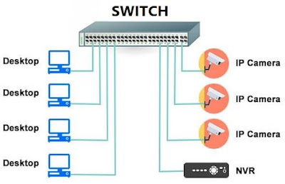
First place the recorder on the network if you already have not. If you are unfamiliar with how to connect the recorder to the network, below are quick and easy to follow videos on how wire the recorder to your network, and enable DHCP to get a dynamic IP address from your router.
The first step is to connect the NVR to the main router in your network. This would be the router your PC is connected to so you can access the recorder over the LAN (Local Area Network). It is imperative that you are on the local network to follow this method.
Next enable DHCP inside the recorder's menu interface using the menu interface shown on your monitor. We usually enable DHCP already on recorders we ship. You may find it already enabled. Note the IP address of the recorder as shown in the last step in the video below. You will need that IP address to access the recorder over the network.
Once you have the recorder on the network, use the IP address assigned to the recorder over the local network by your router to access the recorder using a web browser such as Firefox, Chrome, or Edge.
If you purchased from CCTV Camera World, the video below provides comprehensive instructions on how to change your DVR recorder's resolution using Firefox. You can Chrome or Edge as well. If you have any questions, please email our support team on ssaintegrate@gmail.com
Method 2
If you still have video output being displayed by one of the monitors on
the digital video recorder or network video recorder, then it's simple to change
the display resolution using the menu interface on the recorder. Depending on
whether you have a DVR or NVR, the steps to change the display resolution are
slightly different.

Changing the monitor resolution on a DVR
or XVR
Keep in mind that 4K DVR recorders are capable of 4K display output over HDMI, but the VGA port cannot display 4K video. VGA technology maxes out at 1080P. Once you set the main HDMI output to 4K, the VGA port will automatically become disabled. The process to have either or both the HDMI or VGA port working is explained in the video below.
Changing the monitor resolution on a NVR
Similar to the DVR and XVR recorders we carry, the NVR recorders offer both HDMI and VGA output. Some NVR models even have second HDMI port that is a spot monitor, and that is limited to 1080P just like the VGA port.